WTPA v0.95 ISR Speed Characterized, Code Revs, H/W Changes

Online in 2k9, my ducks.
So sometimes, contrary to common blogline belief there are times when I’m quite busy even when I’m not posting. This New Year / Holiday period was one of them. There are some big advances on the WTPA front:
First, all circuits and modes are totally functional. The resampling problem I was having had two roots. First (and lesser of the two) the input impedance of the AVR’s A/D converter is actually a lot lower than I ever realized. In the datasheet Atmel recommends that you don’t drive the ADC with anything less than a 10k impedance but I actually found that an input resistance as small as 470 Ohms still
produced a noticeably smaller waveform at the ADC input pin than driving the pin directly from the output of an opamp. This was easy (though annoying) to fix — it requires another op-amp section and a redesign of the summing amp into the resampling ADC input. The only unfortunate thing about this is that it will drive the cost of the final device up for you, dear customer, and this kit is already, as they say in France, tres cher.
Still, I made a decision a long time ago that when I design things for me (as opposed to the toy world) I will always err on the side of badassery rather than cost, because I can. And because everybody wants to be a baller, right?
The other (more significant) problem was a Read-Modify-Write issue in the audio ISR. OMGWTFBBQ, was it hard to find! When is a NOP not just a NOP? When it lets you sync an output port you’ve just written to with its input latch. Weird, weird bugs from that one, to be sure. And fixing bugs in my code is, like, totally free!
In other important news I bothered to scope out the speed of the audio IRQs and compare them to the old WTPA. As I had hoped, there was mondo improvement on that front:
- WTPA 0.9, Time in IRQ:
- Recording / Playback: 22-24uS
- WTPA 0.95, Time in IRQ:
- Recording: 5.8uS
- Playback: 7.5uS
- Resampling/Overdubbing: 9.0uS
This means that we could now sample at 44kHz (CD quality — remember CDs?) without breaking a sweat if we wanted to! Of course, I’m not sure how much good that would do us since the ADC on the AVR is already “not-so-accurate” at the paltry 24kHz I’ve got it set to now. But hey, the headroom is there if you all want to get your overclock on.
Practically this means that the processor now actually has some time to get some work done other than audio, which is good.
So the final hardware related issue in this animal is the jitter generator. The way it was originally designed the jitter generator used a PRBS white noise source to mess up the clock signal, and it worked! Sort of.
It became apparent that when the “jitter” control was at maximum, the knee frequency of the filter on the white noise became the dominant interrupt frequency. In English: The fastest noise waveform actually determined the clock frequency in a totally deterministic sounding way.
Since this frequency was different than the clock frequency, you would hear a “jump” in sample rates when adjusting the jitter. This sucked. Right now I’m trying to get the jitter to mess up clocks of all frequencies equally well without inserting a dominant frequency of its own. Meaning a jittered-up 600Hz clock will still have a frequency of 600Hz, it will simply have a totally random duty cycle. (You know, like peak-to-peak displacement, like Wikipedia says under “Jitter”).
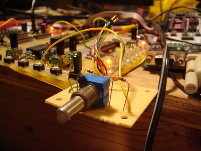
After fiddling around with another analog solution (pictured above) and then with some circuit sketches using AND gates and JK flipflops I realized that the best way to do this (everybody all together now) was IN SOFTWARE. I can’t decide if it’s sad or not that it always seems to be that way. Anyhoo, once I’m done with that it’s time for new boards.
Oh, and my birthday is coming up in a little less than a week. Send me naked pictures, or LOLCATs or something. Xoxoxox.
Tags: Analog, C Programming, Design Philosophy, Device Characterization, Hardware, ISRs, WTPA, WTPA v0.95