Posts Tagged ‘Analog’

WTPA2 Proto Starting to Pwn

Monday, September 20th, 2010

So the first iteration of WTPA2 has some dumbass mistakes — bus problems during flashing hardware (missing pullups), some switch latch goofiness, and turns out all those RC filters in the encoder datasheet really ARE a good idea. However, once all the traces got cut and the little merce-resistors got in place, the thing works great. The VCO is spot on. More importantly, so is the FLASH MEMORY! The SST flash kinda sucks in that it’s not fancy and requires you to manage erasing-before-writing and demands paying attention to buffering and stuff, but you can totally turn off WTPA2 and turn it back on and keep playing with that perfect burp sound you made.

Logic analyzer bus-sniffing.

Also, equally excitingly, the ISR has gotten A LOT FASTER — this proto recorded and played back just fine at 45kHz. A lot of this had to do with taking some very good suggestions from Olivier over at Mutable Instruments (of the Shruthi-1 fame) who is a great programmer and shamed me out of much laziness in my code.
As if that wasn’t enough, I finally licked the lion’s share of the noise sources that plagued WTPA1. I’d always been really careful about analog signal routing, but I’d been pretty cavalier about ignoring the hell out of some of the “Analog Noise Cancelling Techniques” in the Atmega datasheet. Turns out I traced most of the noise back to on-chip activity which had to do with reading and writing to the SRAM (toggling GPIOs) while the ADC conversion was taking place. I moved some of the accesses around and that NAILED it. Like, totally duh!

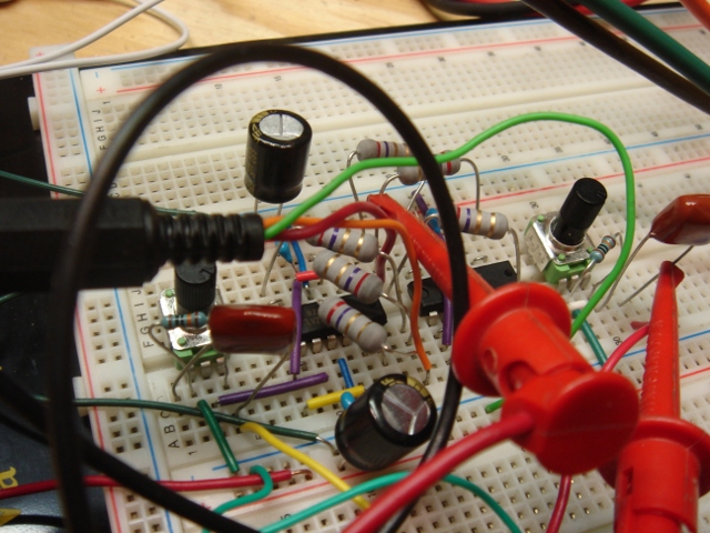
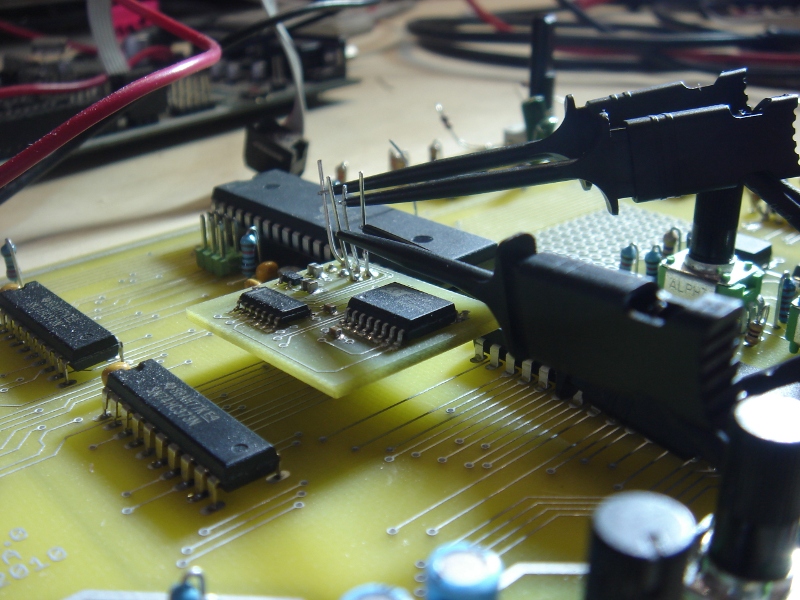
Also, re: the picture — I bought one of those Saleae Logic analyzers the moment they started supporting Linux because it seemed like a cool toy. But it’s actually really useful and works great! In addition to actually seeing what’s going on over the bus (as attached here) it’s REALLY handy for timing ISRs. Like, you toggle a pin high when you vector, and then low again when you exit. I always did this with a scope, but the logic analyzer is great because it records a lot of them and you can analyze variation, see what happens between several different calls, use many channels, etc etc.

Anyhoo, WTPA2 had an exciting week. It may take a break for a minute as I have a really busy winter coming up, but still, good time.
xo
TB

4046 VCO Final Breadboard Proto

Monday, June 28th, 2010

So this weekend marked the last screwing around (breadboarded, at least) with the VCO design for WTPA2. I knew that I could get the frequency range I needed out of a 4046 based VCO with a current sink in place of a frequency setting resistor but I was a little worried about temperature drift and very low frequency performance. Just for shits, I gave the circuit above a shot. It replaces the current sink with a standard two-transistor current mirror. The two devices above are crappily thermally coupled with a piece of heat shrink.

What I found with this is that temperature performance wasn’t too much better. It was still pretty easy to get this VCO to go crazy with the heat gun, although it was possible to get it to go crazy BI-DIRECTIONALLY based on the direction you were slathering on the sweat. Cute, but not useful.
One thing that WAS cool is that the current source compliance was great! The control voltage could get a lot higher than it could with the one-transistor sink before saturation, I assume because of the lack of emitter resistors in the circuit. Still, that was like a consolation prize.

So I caved and built this:

Here’s the schematic for it:

It’s what all the docs I saw suggested originally (a closed loop current sink where the op-amp compensated the temp drift of the transistor) and it totally works and does what it’s supposed to. The only annoying thing is that at VERY low currents the device is non-linear, but what are you gonna do. At a hundred Hz sampling rate all samples sound like farts anyway.

The CV has to be kept below about 2.2v to keep the transistor from saturating (the VCO goes nuts when this happens) but you can fix this with a divider on the input. The range with these components is about 0-20kHz with a CV from 0 to 2.1v or so.

Now I gotta figure out what to do with that other half of the 358. I sort of don’t want to pass it audio, because it’s a recipe for coupling noise into the circuit. We’ll see….

This week I’m working on the board layout for the first WTPA2 revision. I expect the next post here will be about that.
xo
TB

WTPA2 4046-based V-to-F Circuit, take 2

Saturday, June 12th, 2010

Boom! Current sinks all the way:

Because I am late to a BBQ I will not bother here to kick on the corporate dog and grumble about how not a single Rat Shack in downtown Brooklyn sells solderless breadboards. I will however sing the praises of H&H (buy that book. I’m not kidding) and the value of the current sink in the previously discussed VCO clock circuit. I soldered this mess up on some perfboard and in short order had a VCO that happily went from DC to >> 1MHz! The linearity is TERRIBLE, but it proves that the range is there. I’m pretty sure I can fix it adequately for my needs with just fiddling with the passive components in this circuit. Hopefully. Here’s the schematic, captured in time honored analog fashion:

Those component values are way stupid, but I think this is the topology. I may yet get away without the op-amp. Live and learn. And happy BBQing.
xo
TMB

WTPA2, Current Sinks, and the 74HC4046

Wednesday, June 9th, 2010

So once again somebody on the forum came through and found this guy’s page about designing a switched capacitor filter, where he talks about using a CURRENT SOURCE (sink, actually) instead of a resistor on one of the 4046’s frequency setting pins. This was a real forehead smacker. Thanks Kyle (erschlagener) for the heads up, and thanks to Tim for putting that out there in the first place!

Requisite googling found an EDN note about this, too:

Which claims a 1000:1 frequency range out of the 4046’s VCO!
It also confirms what I’d found on the breadboard before, namely that the 4046’s frequency output is not particularly linear outside of about 1v-4.75v, and that inside there you can expect to get about a decade of range. So I felt less dumb.

This note also has the bright idea of putting the sink in the feedback loop of an opamp, which almost certainly helps linearize the sink’s behavior at low voltages by getting rid of base current related weirdness.

Enter a quick trip to findchips for some pricing data. Turns out that the 4046 and a transistor are certainly cheaper than the LM331, although they take up more real estate. Even throwing in an cheap LM358 still costs less than the LM331, although the savings start to get less significant. Now, if there was some good use for that second op-amp in a ‘358, that’d be something…

This recalls some quote I heard and want to attribute to Jim Williams, though I can’t recall exactly where it’s from, about how in modern circuits like 80% of the thing is digital and takes 20% of the time to design, whereas the 20% that’s analog takes the 80%. Sometimes it does seem true, although it might just be (for me anyway) that the analog parts are a lot of fun :-)

Back to the breadboard!
xo
TMB

Adafruit Headphone Amp Design

Saturday, June 5th, 2010

So a few weeks ago I met up with my old buddies Limor and Phil at Adafruit Industries and was griping about work being slow, and they were like, design us a kit.

So I did. They wanted a headphone amp which, in their words, “didn’t suck”.
This was really exciting to me! I do a lot of contract work, but I almost NEVER get to do something that’s exclusively analog! Granted, an HPA is not exactly pushing the boundaries of silicon magic in 2010, but I’ll take what I can get. It was a blast. I got to figure out phase margins and characterize ringing and overshoot and make a cable mess (and then worry about the capacitance of it) and just generally get my party on. Plus it was a chance to flex skills in an arena that is full of a lot of crappy designs.

And though the thing is GPL’d,, they did ask me not to go into specifics here or post any schematics or juicy bits UNTIL they have the product out, so until that happens I’m afraid I can’t go into a lot more detail.

Can’t wait to see them lay it out.
Thanks guys!

ALSO — I’d be remiss in not mentioning my friend Shea who had a lot of great advice on this circuit and who has generally forgotten more about audio electronics than I’ll ever know. He re-did the Trident A Range board at Soma Electronic Music Studios when I was back in embedded diapers and let me help re-cap some modules and generally be a solder monkey. I got paid $10 an hour for that and those were still some of the most exciting electronics dollars I ever made.