Posts Tagged ‘Analog’

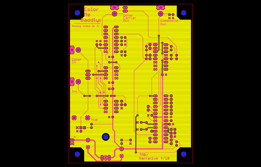
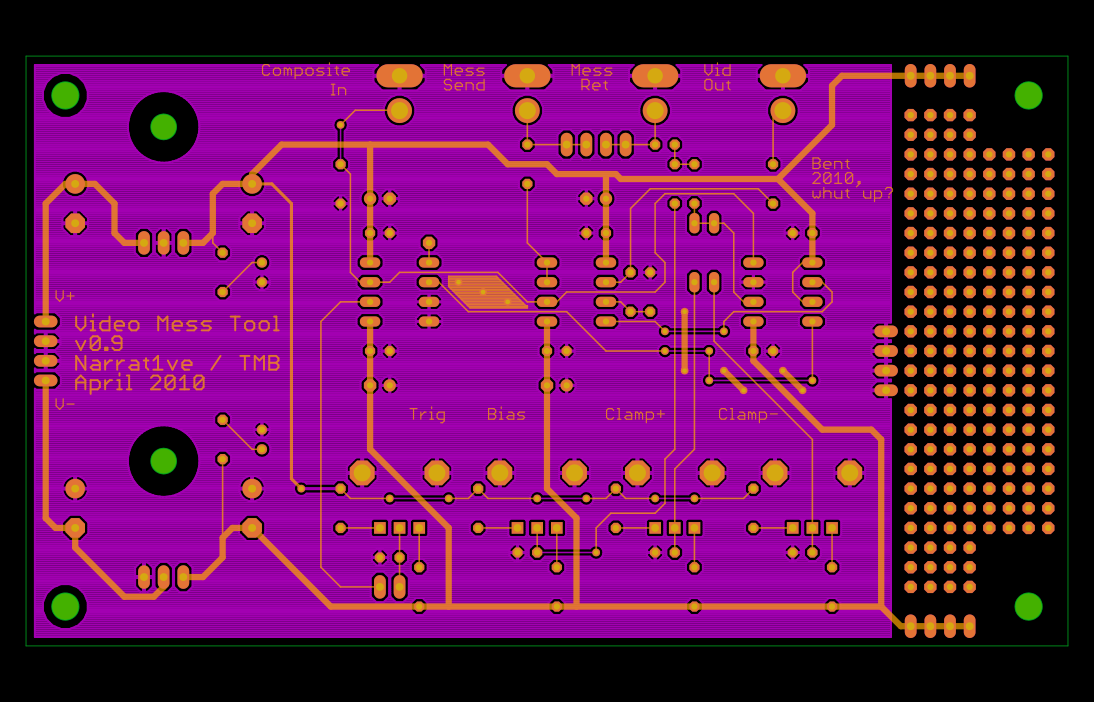
Video Mess Tool Assembly

Wednesday, April 21st, 2010

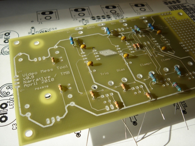
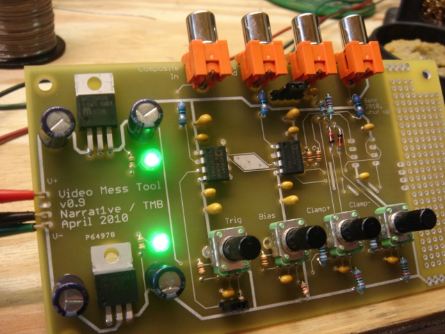
Yesterday the PCBs for the Mess Tool came in and I populated them. Like a big dummy I forgot to order the LT1203, so testing was relegated to the bench until today. This turned out to be a good thing, since of course there were legit problems which needed attention.
You can see from the pics that there’s a proto area in the mess tool. That ended up being a good thing. Part of the circuit is a set of clamps which let you keep whatever gnarly signal you’re injecting into the poor unsuspecting TV from spilling over into the sync region.

These clamps ended up being the source of some trouble — they were mushy passive clamps which put a 47k in series with a video signal, which it turns out is TOO MUCH, since all that pretty ground plane (and the IC inputs, and whatever other parasitic stuff is going on) contributes significant capacitance at color frequencies. The diodes I was using to clamp to a reference (SD103s) turn out to also have a 50pF capacitance or so at 1MHz, which again, counts for a lot.

This means that the video through the “snarled up” section tended to just get filtered away to nothing. The solution was (well, will be, I’m still building it) an active clamp which lowers all the circuit impedances and generally burns up more current.

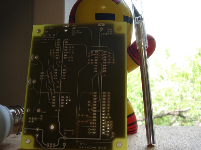
The mux came in this morning (and Digikey was out of parts in the correct footprint, grumble) as did the boards for the synth and some low-capacitance diodes. So today will be busy. More soon.

Also. Not to get gooey, but man do I love hardware. Really. I forget that in the good old days it was me and a scope and I never ever wanted to learn to program. You know, when men were men and all that.

Xoxo, TB

Color Me Baddly Gerbers — a companion video tool.

Tuesday, April 20th, 2010

Just for grins, while I was waiting for the PCBs to come in, I decided to lay out a new design for color synthesis that I’d been fooling around with. This, again, is the gerber file.

The sync and blanking circuits in the above are fairly pedestrian — they’re just an AVR running at 14.318 MHz, which controls a 4051 to gate in the correct resistor values to get sync and blanking levels into 75 ohms. This part is pretty much exactly the same as the circuit from Owen Osborn’s old CA synth (which is a really elegant piece of engineering, I think). The AVR generates the colorburst and color carrier also using a hardware timer to divide the crystal frequency by 4. This means this prototype ain’t gonna do PAL. Sorry.

To my mind, the really interesting thing is the way in which color gets generated. Hue is encoded in analog composite video by _PHASE SHIFT_ of a carrier wave. Someone very smart and very good at electronics figured that out a long time ago. I’ve built synths in past which use the AD724 (lame) and varactor diodes to give continuously variable integration.

The varactors are actually a pretty badass way of doing it — they’re fast and kinda nonlinear and totally work, but it requires A LOT of stages of this to get 360 degrees of shift (enough for all the colors a TV can display). Also, (in addition to not being super cheap) the really good varactors are small SMT devices. I personally don’t care, but some of the cave-people with soldering irons who frequent this site occasionally express concern about this sort of thing and their poor tired eyeballs etc etc. Generally when this happens I turn up the Brandenburg Concertos and have my manservant pour me another Campari spritzer, but this time I decided the unwashed masses should have some cake too.

So.

It took a lot of searching and fiddling to find something that I thought would work, that was both elegant and cheap and didn’t require exotic components or a sensitive board layout or weird supply rails or whatever. I had this suspicion that a PLL could do what I wanted, cause you know, its job is to party with phase. PLLs regularly work at or above colorburst frequencies (3.58MHz) which is also good because it means they aren’t on the edge of some spec.

The other idea I had (a voltage controlled all-pass filter) was generally too hard to do at frequency ranges that high (the LM13700 won’t slew anywhere near that fast, for instance). Other than designing an OTA which works at those frequencies (on my list of things to do, along with dating supermodels, designing invincible armor and generally running Stark Enterprises) I wasn’t sure how to implement this in a simple way.

PLLs are not the easiest circuits to understand (for me, anyway). But they are cheap and ubiquitous and many very smart people have written a lot about them. Eventually I stumbled across this circuit in EDN. The description with it is brief, but pithy, and explains the essential details of what I wanted to do.

Armed with this I was able to create a new design, standing on the shoulders of great nerds past. And when UPS shows up, I’ll know how well it (as well as the Mess Tool) works out!

Xoxo, TB

Video Mess Tool, or, Snuggling With Sandin (for a Bent 2010 lecture)

Friday, April 16th, 2010

The pretty pretty gerbers for a new video tool. This device will hopefully allow you to take all the precious bits of composite NTSC (or PAL, I guess) video and keep them safe, while mucking with the rest of the signal. Sync, blanking, and colorburst are separated with a level comparator, and a mux allows you to inject new signals or perturb the old one. It’s analog, and based on the AD828 op amp, the AD8561 comparator, and the LT1203 video mux/buffer. For one, I hope it works. For two, I hope it looks awesome. Stay posted!

WTPA2.0 Hardware Feature List Announced!

Monday, April 5th, 2010

It was with great pleasure that I posted the initial list of hardware features that will make it into the next hardware revision of WTPA on the Narrat1ve forum. Until you start seeing boards rolling out, there’s still time to change this stuff, so feel free to let me know what you think and what you’d like to see.

Here they are, as well as what they do for the kit and what they’ll do to the price:
================================================================

1.) WTPA 2 will have 8 controller buttons and not six (the very first one had 5 I think). This will allow us to avoid the dreaded 3-button combo when accessing functions. However, this means two more buttons, and one more shift register IC and socket. This costs more.

2.) There will be a through hole RAM chip. This means the whole kit will be through hole (no smt). This will probably cost about the same, but the board will need to get a little bigger.

3.) The analog sample clock will be based on a 4046 and not an op-amp relaxation oscillator. I can do this because I don’t need the extra op-amp section for overdubbing. This will cost a little less and will also allow CV input to the clock.

4.) The control pot will be replaced with an endless rotary encoder. This will help in all kinds of subtle ways. This may cost a hair more. Given enough pins, I may add a second encoder.

5.) The MCU will be either an Atmega644p or 324p, simply because I want the freedom to add new functions and we’re pretty much out of flash memory on the 164. This will also give us more RAM which may help some of the granularizing functions, and may be able to help with ISR speed if I’m smart about buffering. Those chips are still a 40-pin dip. They cost more.

6.) Some of the values in the analog section will change, which will result in slightly more headroom. This will probably cost about the same.

7.) The bus which is just hanging out doing nothing on the v1 WTPA will be used to access permanent memory. There will be an optional daughterboard which will contain a flash memory chip and will be able to store either 8, 16, or 32 samples depending on how some pricing and availability works out for me. I _might_ implement a sample loader via MIDI. Maybe. The daughterboard will come assembled (all that stuff is small smt biz) and will cost more than $20. Not sure how much more. So permanent storage will be optional.

8.) Instead of a hardware goodie bag, there will be another optional board which will have PCB mounted jacks for MIDI, Audio, and DC. Second to the RAM chip, most build problems in V1 were in the wiring. This should eliminate that problem. This board will mount under the main board. This will _probably_ be more expensive than the goodie bag, but may not be depending on some of the jack pricing.

9.) The routing from the input amp to the AVR will change A LOT. This should lower the noise floor a little.

10.) Because of all these changes, the board will be bigger. Probably not a lot bigger, though. My guess is the price will go up a little too.

Ph’nglui mglw’nafh Remoc R’lyeh wgah’nagl fhtagn, or, Everybody Loves Remoc

Sunday, January 17th, 2010

At the end of January I drove back to the city of heavenly taquerias and got jiggy with installing new brains in Remoc, just the cutesy wootsiest Elder God you could ever hope to meet!

Our boy assumed this position for many hours. Quoth the security ladies at the front desk, “Your Monster is all Drunked over!”

Here’s what the sensors look like in vivo. The little wire goes to a sheet of copper tape which is adhered to the inside of one of Remoc’s surfaces where he’ll be sensing touch (for instance, his finger — you’ll never guess what happens if you pull it). These plates are all of different sizes and shapes, and of accordingly make for different signal strengths on the output. They are also pretty close to one another sometimes and it certainly seems from looking at the ADC readings like there are some irritiating interactions between some sensors. If I did this again, they would each have an enable line and be polled sequentially. But.

The little boards get stuck down somewhere convenient and close to the tape, and then the more-or-less DC sensor signal is shuttled back through a cable.

Finally, the guy who sculpted Remoc managed to set his entire body cavity on fire shortly after all the copper tape and wiring was installed. This adds a real “wild card” element to the sensor system which keeps it fun!

Anyhoo, after a long install, he was back up and gibbering, and there was much rejoicing!


[Ed note: since this time, word has again arisen from the West that the cultists are stirring. It is likely this is not the last time we will sojourn to the Comer, dear reader, or as I like to call it, “Baby Boo Miskatonic”]