Posts Tagged ‘Electronics Advice’

Care and Feeding of the HP 6632b

Friday, July 2nd, 2010

Yesterday Narrat1ve got a new (sort of) bench power supply in the form of an eBayed HP 6632b!
You can read what HP says about it but it basically kicks as much ass as I could really want or expect a single output PSU to kick. Until now I’d been using a couple of Tektronix PS503a units (which are pretty great, actually) and a Power Designs TW6050a (which is very heavy). However in the course of figuring out some VCO stuff I found myself really wanting to be able to step by small numbers of millivolts and trust with some certainty that what I was asking for was what I was getting (and the 6632b’s microamp measurement is handy for embedded stuff, too).
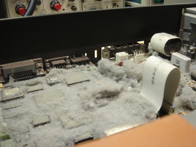
Anyhoo, the unit showed up all kinds of Dirt McGirt:

And had all kinds of goofy user settings in it. Ebay buyers of HP supplies take note:
Because I’m the kind of guy who reads the manual (and because a buddy of mine had just gotten one of these) I knew that it should have powered up in a certain state (namely, with the output disabled!) and it didn’t. One of the cool things about these supplies is that they talk RS-232 in many languages. One of the annoying things is that this one happened to be set to a language which sucked (COMPatibility, I guess an older GPIB compliant standard) and didn’t allow you to do many of the things that you can do with SCPI even from the front panel. After some head scratching and a LANG change this was resolved. The next problem was the fact that the front panel meter was a little off from what I was measuring at the output. “Lucky for me I have a fancy bench meter, and it’s easy to calibrate this thing,” I thought. WRONG.

Somebody had set the calibration password on this in times long gone by and there ain’t no changing it. I got the service manual and it turns out you can defeat password protection by flipping a DIP switch inside the chassis. This is when I took it apart and discovered the dirtball above.
After much swearing, compressed air, and windex, the inside of the chassis looked like this:

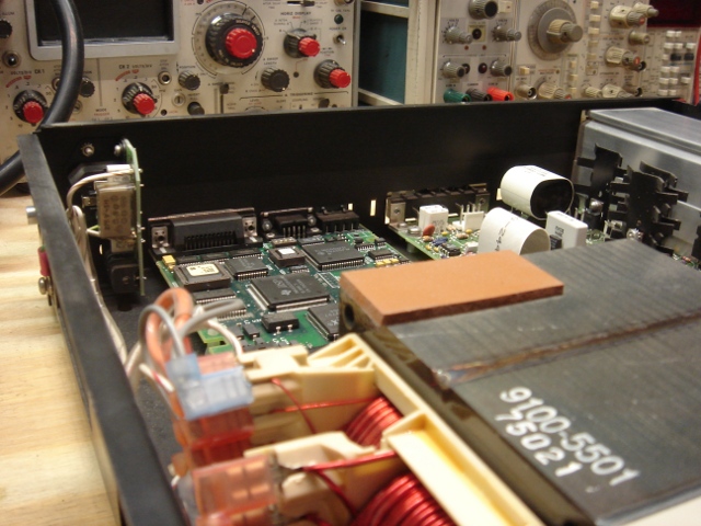
In addition to letting me get at the DIP switches, this also gave me a spiritual sense of wellness at having un-funked a nice piece of gear that somebody had really let go. It also made me less worried that there were secret vermin in my apartment that were taking refuge in my bench. It also made the fan run quieter.

In the course of doing this I also realized that the goobers who used this thing before had removed the terminal block jumpers from between the SENSE and OUTPUT screws. I replaced them. Who are these people? Were they so fancy they were using 4-wire? Who does that? Somehow I’m suspect.

Finally, I did the calibration. When it was done, the front panel meters were dead on, and the output voltage was within 0.2mV (worst case) of what my fancy meter says it should have been. Not perfect, but not bad for an eBay bench supply!

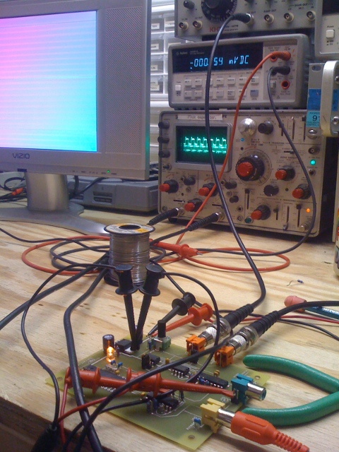
Finally, I installed my own “Front Panel Connectors” so I could use the thing without monkeying with the back:
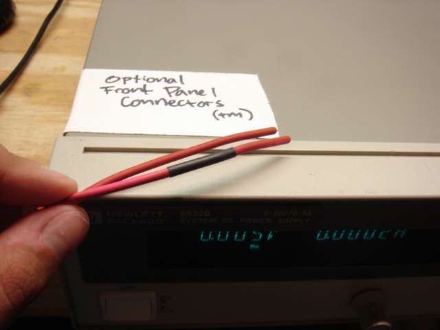
Baller status!
xo
TB

Bent 2010 / Video Mess Tool / Color Me Baddly Breakdown

Wednesday, April 28th, 2010

So, Bent 2010 is over, and as such my arbitrary deadline and excuse for spending time and cheddar on this particular device has been pulled. The above are the final circuits I presented with at the lecture.

The thing on the left is “Color Me Baddly” from the Gerbers below. It’s a color video synth (based on PLLs) which takes a CV in for the color generators (which is peculiar about its input range, to be sure). It also takes a CMOS level input which can invert the color carrier phase by 180 degrees. On the output side it spits standard composite video as well as a CMOS level color carrier (with no sync, blanking, or burst).

The PLL color tracking is pretty good! But not perfect. The PLL keeps lock over a range of a few volts in, and tracks as high as 30+ kHz, which is better than I’d hoped. It took a lot of fudging the loop filter, although the RC calculations weren’t very hard. The invert is a cool input, which originally I just made for the proto because I needed it to to get 360 degrees of color. But in general (not suprisingly) I’m finding that the more inputs you have to things like this the more weird interactions you can get between modulating signals. So I think the invert is here to stay.

The thing on the right is the “Video Mess Tool”. The circuit is different than I originally intended w/r/t the clamping circuits, which had to be made active. The crap you see over in the far right side in the proto area is that new clamp. The clamp ranges changed a little, too. The LT1203 and AD828 and AD8561 are all pretty great ICs and basically do EXACTLY what you’d expect. Even using the opamps in unity gain for the clamps (not recommended) worked without any hitches.

I think this circuit would look a lot cooler with a window comparator — something which muxed many different mess or non mess signals and was smarter about selecting when, and which had a _still_ better series of clamps for restricting signal range. A HSYNC+burst specific monostable following the comparator would also probably not be amiss, although some of the glitchiness would be eliminated. This could be selectable — “sloppy sync” vs “Teutonic Sync” or the like.

The thing in the back is a color synth I made for Christams 2009. It uses varactor diodes instead of a PLL and is its own weird animal. There are pics of that here.

So before finally throwing these guys into the mothballs for who knows what/how long, I made a couple more videos. They showcase some of the more complicated waveforms that can be generated. Neither has any audio involved; both use input from function generators. The above uses the mess tool to mux in a rainbow from the color synth into golf. The lower one is basically two synths being muxed together and inverted all around multiples of 60 Hz, which makes the trippy horizontal band.

Naturally, all this stuff looks better in person; taping an LCD screen with a webcam is not exaclty the height of majesty. And there’s a couple more tech notes on the Narrat1ve youtube channel.

This might be it for this project for awhile, so feel free to write to me or get on the forum if there’s anything else you’d like to know about!

[NOTE: Collin Cunningham of MAKE took a pretty kickass video of my lecture at Bent, and one day I’ll put it up here. Thanks, Collin!]

Xoxo, TB

Color Me Baddly — New Hit Single “Arbitrary Phase Shift” Out Now.

Thursday, April 22nd, 2010

So you can see this PLL video synth guy working his magick here if you look at the scope. That’s a reference colorburst on the top trace, and the bottom trace is that same signal being shifted back and forth around the reference. That’s how NTSC is fixing to get its hue on.

Doing this is the hardest part about generating a color video signal from scratch. “Real” color encoding devices (in NTSC) use something called “IQ Modulation” (really) or QAM (Quadrature Amplitude Modulation) which is what I will shoot for in the next version of this.

I mean, real devices now use processors and ASICs, but.

A close up of the board after he got stuck on some hot pink acrylic.

xo
TB

Color Me Baddly Gerbers — a companion video tool.

Tuesday, April 20th, 2010

Just for grins, while I was waiting for the PCBs to come in, I decided to lay out a new design for color synthesis that I’d been fooling around with. This, again, is the gerber file.

The sync and blanking circuits in the above are fairly pedestrian — they’re just an AVR running at 14.318 MHz, which controls a 4051 to gate in the correct resistor values to get sync and blanking levels into 75 ohms. This part is pretty much exactly the same as the circuit from Owen Osborn’s old CA synth (which is a really elegant piece of engineering, I think). The AVR generates the colorburst and color carrier also using a hardware timer to divide the crystal frequency by 4. This means this prototype ain’t gonna do PAL. Sorry.

To my mind, the really interesting thing is the way in which color gets generated. Hue is encoded in analog composite video by _PHASE SHIFT_ of a carrier wave. Someone very smart and very good at electronics figured that out a long time ago. I’ve built synths in past which use the AD724 (lame) and varactor diodes to give continuously variable integration.

The varactors are actually a pretty badass way of doing it — they’re fast and kinda nonlinear and totally work, but it requires A LOT of stages of this to get 360 degrees of shift (enough for all the colors a TV can display). Also, (in addition to not being super cheap) the really good varactors are small SMT devices. I personally don’t care, but some of the cave-people with soldering irons who frequent this site occasionally express concern about this sort of thing and their poor tired eyeballs etc etc. Generally when this happens I turn up the Brandenburg Concertos and have my manservant pour me another Campari spritzer, but this time I decided the unwashed masses should have some cake too.

So.

It took a lot of searching and fiddling to find something that I thought would work, that was both elegant and cheap and didn’t require exotic components or a sensitive board layout or weird supply rails or whatever. I had this suspicion that a PLL could do what I wanted, cause you know, its job is to party with phase. PLLs regularly work at or above colorburst frequencies (3.58MHz) which is also good because it means they aren’t on the edge of some spec.

The other idea I had (a voltage controlled all-pass filter) was generally too hard to do at frequency ranges that high (the LM13700 won’t slew anywhere near that fast, for instance). Other than designing an OTA which works at those frequencies (on my list of things to do, along with dating supermodels, designing invincible armor and generally running Stark Enterprises) I wasn’t sure how to implement this in a simple way.

PLLs are not the easiest circuits to understand (for me, anyway). But they are cheap and ubiquitous and many very smart people have written a lot about them. Eventually I stumbled across this circuit in EDN. The description with it is brief, but pithy, and explains the essential details of what I wanted to do.

Armed with this I was able to create a new design, standing on the shoulders of great nerds past. And when UPS shows up, I’ll know how well it (as well as the Mess Tool) works out!

Xoxo, TB

The Joy Demon Cont’d

Sunday, January 10th, 2010

So sometime at the beginning of 2010 the sick children of Chicago set up a fuss looking for their monster again. You could hear them all the way from Brooklyn. Again, my guilt was heavy. Again, I made some stuff.


An introduction of what Remoc does is in order I guess. He’s basically a bigass toy that senses when little kids touch him in different spots and plays various games with them. He laughs, he cries. He may or may not be better than Cats. He also goes to sleep at night, sings songs, and has a weird interactive thermometer. He farts a lot. When he behaves, he’s kind of fun.

His memory and play pattern live on an SBC designed by my buddy Todd Squires which we used at the old toy company and affectionately call the toybrain (version 4). The TB4 was fine.

There was no real way to salvage most of the rest of Remoc’s old brain. There was a crappy class AB audio amp I put in which got way too hot, his touchsensor circuits were noise prone and also temperature sensitive, and his LED supply tended to go out of regulation when too many lights in the thermometer stayed on, and he got confused easily about time-of-day stuff if you turned his supply off. His eyeballs were light bulbs which burnt out (that was a committee decision, but). None of this was good.

His new brain boards (above) dealt with all this stuff. 2010 saw Remoc get new MOSFETs to run all his lights, a new audio amp, and a proper RTC with a ginormous battery for backup. More importantly, he got a bunch of precision opamps and a multichannel ADC to handle input from the touchsensors.

The touchsensors were actually fun to make. They’re an AVR which generates a crystal derived square wave (laziness on my part, and tunability. The generator could have been a logic gate or any crystal clock circuit really, although the programmable chip provided fudge room which I didn’t [and hopefully won’t] need) and drives it through a resistor to whatever gnarly sensor plate you have, and then filters and rectifies what’s left. They use hand capacitance to form a variable RC filter; the output of this device is a voltage which is inversely proportional to the capacitance at the sensing node. Not perfect, but pretty good. These sensors also use 1/8″ cables to carry power, ground, and signal, cause 1/8″ cables are cheap and promised to make wiring the beast a lot easier.

The thermometer. Some SMT LEDs on a stick. Yaaaawn.

All this stuff got packed up to schelp to Chicago.