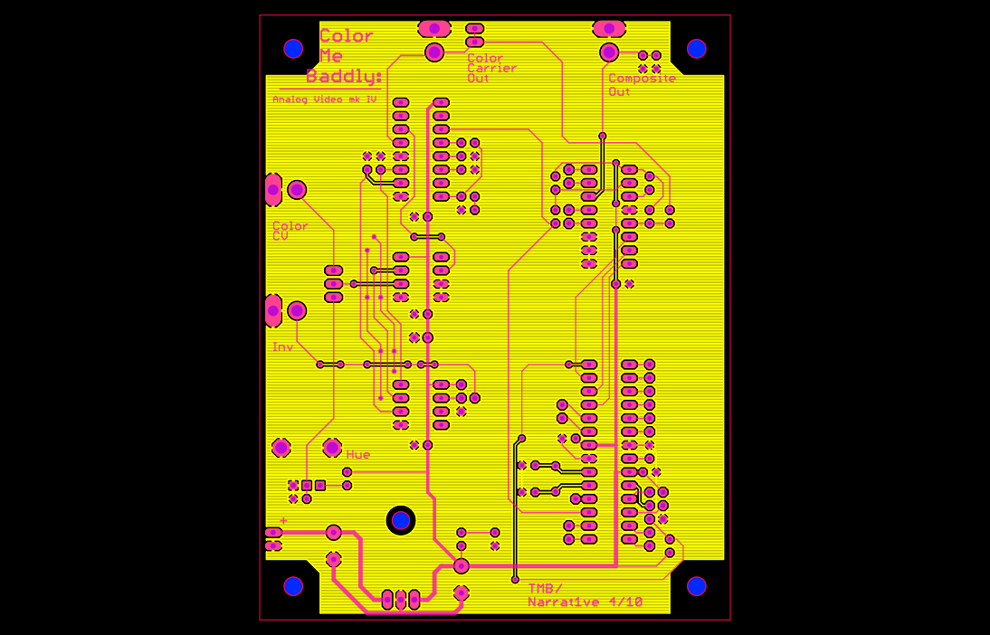
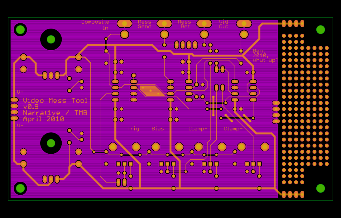
Color Me Baddly Gerbers — a companion video tool.
Tuesday, April 20th, 2010Just for grins, while I was waiting for the PCBs to come in, I decided to lay out a new design for color synthesis that I’d been fooling around with. This, again, is the gerber file.
The sync and blanking circuits in the above are fairly pedestrian — they’re just an AVR running at 14.318 MHz, which controls a 4051 to gate in the correct resistor values to get sync and blanking levels into 75 ohms. This part is pretty much exactly the same as the circuit from Owen Osborn’s old CA synth (which is a really elegant piece of engineering, I think). The AVR generates the colorburst and color carrier also using a hardware timer to divide the crystal frequency by 4. This means this prototype ain’t gonna do PAL. Sorry.
To my mind, the really interesting thing is the way in which color gets generated. Hue is encoded in analog composite video by _PHASE SHIFT_ of a carrier wave. Someone very smart and very good at electronics figured that out a long time ago. I’ve built synths in past which use the AD724 (lame) and varactor diodes to give continuously variable integration.
The varactors are actually a pretty badass way of doing it — they’re fast and kinda nonlinear and totally work, but it requires A LOT of stages of this to get 360 degrees of shift (enough for all the colors a TV can display). Also, (in addition to not being super cheap) the really good varactors are small SMT devices. I personally don’t care, but some of the cave-people with soldering irons who frequent this site occasionally express concern about this sort of thing and their poor tired eyeballs etc etc. Generally when this happens I turn up the Brandenburg Concertos and have my manservant pour me another Campari spritzer, but this time I decided the unwashed masses should have some cake too.
So.
It took a lot of searching and fiddling to find something that I thought would work, that was both elegant and cheap and didn’t require exotic components or a sensitive board layout or weird supply rails or whatever. I had this suspicion that a PLL could do what I wanted, cause you know, its job is to party with phase. PLLs regularly work at or above colorburst frequencies (3.58MHz) which is also good because it means they aren’t on the edge of some spec.
The other idea I had (a voltage controlled all-pass filter) was generally too hard to do at frequency ranges that high (the LM13700 won’t slew anywhere near that fast, for instance). Other than designing an OTA which works at those frequencies (on my list of things to do, along with dating supermodels, designing invincible armor and generally running Stark Enterprises) I wasn’t sure how to implement this in a simple way.
PLLs are not the easiest circuits to understand (for me, anyway). But they are cheap and ubiquitous and many very smart people have written a lot about them. Eventually I stumbled across this circuit in EDN. The description with it is brief, but pithy, and explains the essential details of what I wanted to do.
Armed with this I was able to create a new design, standing on the shoulders of great nerds past. And when UPS shows up, I’ll know how well it (as well as the Mess Tool) works out!
Xoxo, TB


