Posts Tagged ‘WTPA’

Component Variation, Or, The Least Sexy Electronics Problem Evar

Thursday, July 7th, 2011

Analog is sexy, we all agree, right? Embedded systems on the other hand, are full of lots of unglamorous problems. Filesystems, say. Inherently un-sexy.

Yawnz

But I think component variation is maybe the best, most un-sexy problem there ever was. The unsexy cherry on the diet sundae. Like, you HAVE to solve it if you are making lots of something or that thing as a population will suck, even though the one on your bench always ruled.

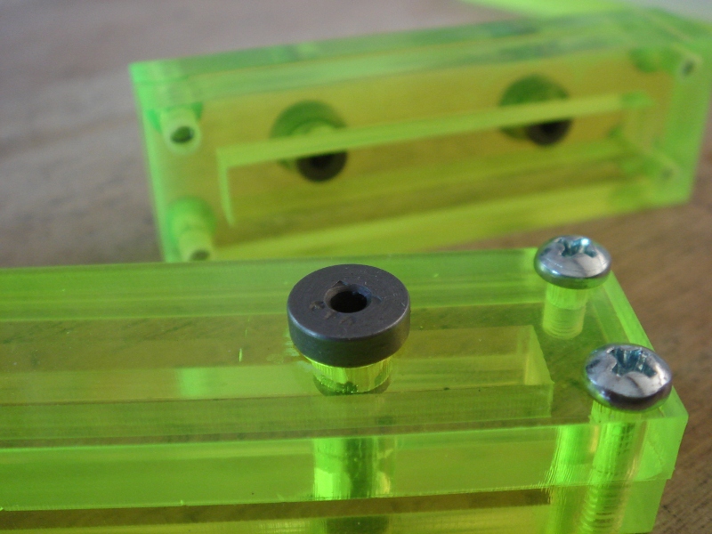
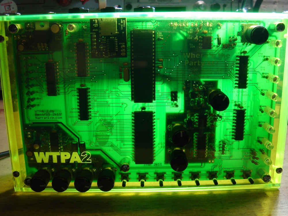
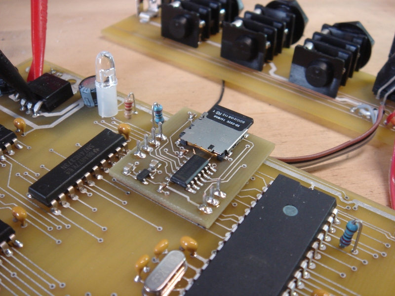
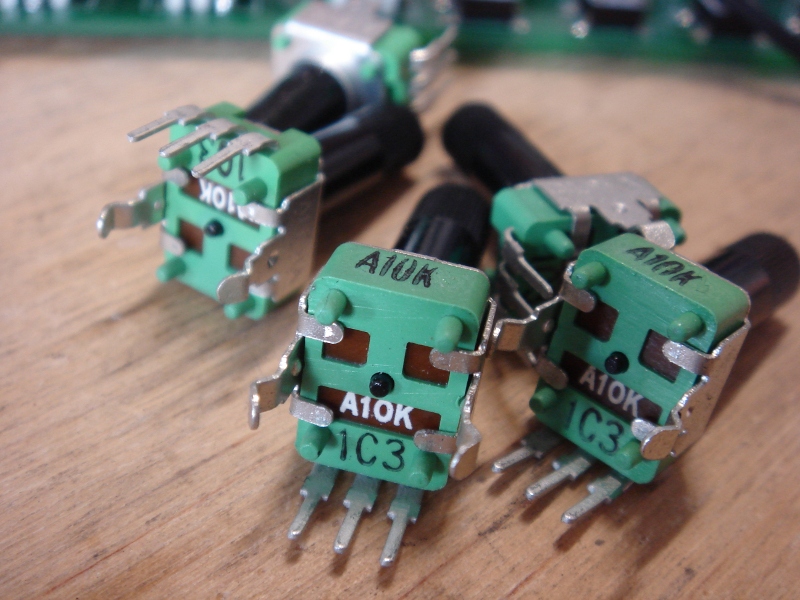
All the pots in WTPA2 are these custom Taiwan Alpha jobbies. There are two values, 10kA and 100kA. The VCO uses one of the 10kAs as a coarse control, and it sets the voltage into a current sink which in turn sets the frequency. I’d been messing with the op amps in this circuit to try and get some performance improvements and “all of a sudden” one of the DUTs didn’t work correctly. At first I figured it was the opamp change, but after a lot of measurement and desoldering and component testing, it turned out one of the 10k pots was really 11.4k. This was a greater than 10% variation!

I’d built a margin in for error, but this was above it, and the current sink was getting too high of a voltage. I tested a dozen pots or so from the bin, and all of them were much less off. Still, since one was off, probably another one could be as well. It could even have been a result of the soldering process. I actually bothered to do a DC simulation at this point (using qucs) and fiddled with the component values until they were all as off as I could imagine them possibly being, and then resized the scaling resistor that sets the upper range of the VCO. It was a really crappy annoying unsatisfying solution, because it means that MOST of the units will be operating at a slower maximum clock than they need to. But that one in twelve or one in 100 will work correctly. Serves me right for getting the cheap pots, but there you go. Margin. Component variation.

Least Sexy Problem Evar.

TB

WTPA2 Clock Characterization & Pulse Shaping

Wednesday, July 6th, 2011

So, after getting back to client work for a minute, I decided to try and nail the clock pulse shaping circuit problem with a more viable solution than throwing in an extra $5 op amp.
The problem with the original pulse shaper circuit was simply that it was designed with a function generator and not a 20 cent opamp in a RC oscillator. The idea was sound (I think) but the values were not.

The real problem is that the square-to-pulse converter has to shape two different clocks — it’s always driving the same IRQ pin, but it can be hooked up to WTPA2’s 4046 based VCO, or the LM358 based on a user switch. The 4046 is HC logic, and has really square edges. The LM358’s edges are not square, and their slew rate seems frequency dependent also. So, you could optimize components for one or the other, but not both. I did some bench tests to figure out what I needed to change to get this right.

Check it. Here’s the rising edge of the output from the VCO:
4046_Edge

And the corresponding output from the pulse shaping network:
4046_pulse

Since we aren’t changing the VCO, this is what we’re gonna call “normal”. The top trace shows a risetime of about 0.1uS (scope is 0.1uS/div, 2v/div) which is quite fast (50V/uS in opamp terms). The ringing here probably has to do with the long ground connection on my probe, and it doesn’t hurt anything except my pride. The bottom trace (the output from the pulse shaper) shows a clean low pulse which is about 6uS long total (2uS/div)
Now, here’s the LM358:

358_Edge

And the corresponding output from the pulse shaping network:
358_Pulse

Waaay different! This is the LM358 at its best incidentally — tested at low oscillator frequencies. At higher clock frequencies it slews even more slowly.
The top trace is 10uS/div, and shows a rise time of about 25uS (it’s 60uS with the clock cranked up to 25kHz). Annoyingly, it has that characteristic LM358 style crossover mess. AND it only gets up to about 4v. The rise time is really what matters though, and it is orders of magnitude slower than the 74hc4046. The bottom trace shows the output of the pulse shaper, trying but not quite making it. That dip never makes zero volts and might last 0.25uS. This doesn’t consistently trigger our interrupt-on-change IRQ.

So, the question was what to do. I tested a TLV2462 opamp (my goto op amp for embedded stuff, made by TI, a tank) and it performed equivalently to the 4046, and the pulses worked great. It’s slew rate was rated at 1.6V/uS, which is about 5 times faster than the LM358’s 0.3 V/uS. So it was faster, but not by orders of magnitude. If I could find an opamp which cost about the same as the LM358 and had a better slew rate, that seemed appealing rather than trying to hack up a circuit on 300 already-fabbed boards. The question was how fast we needed to go.

I settled on three opamps for the test: The Microchip MCP6002 (0.6V/us), the Microchip MCP602 (2.3V/uS) and the Texas Instruments TLC272 (5.3V/uS). A few days later I had them all from Digikey. I tested the MCP6002 first, since it was the cheapest. (0.27 at quantity, as opposed to the LM358’s 0.20) Surprise surprise! It worked great on the first try.
Although I didn’t measure the rise time, it looked clean on a scope. The ouptut from the pulse shaper was 6-7uS which is as good as (and more importantly in line with) the logic chip in the VCO. This was also consistent with the TLV2462.

In conclusion, the cheapest and easiest way to solve this problem is (I think) to eat 0.27 per kit and throw in another opamp. Further, the results are interesting because they show that above a certain rise time, performance remains the same. My guess is that there’s a knee point in that filter, and as long as the dominant frequency of the edge is above it, we’re good to go. In this case, a clean 0.6V/uS output was enough to trigger the shaper reliably.

Now that the results are consistent and I’m in tweak mode anyway, I’ll probably try and get those pulse times down by half or so, just in case the ISR gets faster.

Analog is fun, yo.
xoxox
TB

WTPA2: Straight Up Struggle

Sunday, June 26th, 2011

Last week was hellish.
Srrsly, yo. I forgot how much work this is. I flew my buddy Nick out from Chicago to be in charge of kitting and assembly, and my job was to get the firmware rocking. We had from June 20 to June 24 to stuff 300 kits, 100 jack boards, 100 drilled and tapped enclosure kits, build and test 100 microSD daughterboards, build a dozen assembled units, and get ready for Bent and our Solid Sound panel talk with Moog!

Woes, take 1:
China called and were like, yo man, your main boards are gonna be late. I blame myself for letting it get so close to the wire, and to be fair they were totally sports about shipping the paste stencils and small boards early. Still, with no main boards, I would have nothing to show at the festivals. Eff that. So I called up Advanced Circuits and was like, hook a brother up in the meantime, and they were like BLING BLING. So, I got 27 “Limited Edition” green pcbs, and made some acrylic enclosures to match. Financially, it was retarded. But I have my pride.

Woes 2:
Joe at Prototope really nailed it cutting a ton of enclosures. T&T PlasticLand over by Canal also came through in the clutch with like 100 pounds of fluorescent acrylic with prices that McMaster can’t hang with. However, some dumbass specified that all these enclosures should be drilled and tapped, and those operations alone took DAYS, even with my fancy drill jig:
Fancy

Here’s Nick hating life:
Zzzzz

Woes 3:
That effing pulse shaper circuit (see the last couple posts) was wrong. Of course we didn’t figure this out until an hour before Bent. It was borderline such that it worked _a little_ even though the circuit had not changed since the prototype. The routing and components (though not the component values) had changed, and that was enough. Basically the LM358 had shitty rise times into whatever load the circuit presented, and the effective edge frequency (what the pulse shaper really looks at) was too low to work. I threw a handful of expensive TI opamps into some kits and dragged them out anyway, determined to have something to sell, but I only thought of this after Bent (but before we drove to North Adams for the festival). The new opamps slewed a lot faster and were an effective (if again, expensive, bandaid).

Woes 4:
The microSD card. I came up with new swears for these things:
More 0xFF plz
Originally for this project I bought a crappy Kingston 2GB uSD card for testing from a pre-paid cellphone store near my house. FOR WHATEVER REASON, it turned out to be the fastest, most forgiving device ever. This week, on a whim, I ordered every crappy uSD card between 512MB and 2GB that I could find on Ebay. They all behaved differently. It took days to test my drivers to make sure that all the cards behaved correctly, and there are definitely exchanges in there that you have to do which have pretty much zero to do with the SD spec (or at least the free one). This sucked, to say nothing of then trying to make a filesystem and buffers to read audio in realtime. While card access was rock solid for all tested cards by Bent, I kinda though my sample read-write routines sucked. In the end I threw them out. The devices at Bent could format an SD to the WTPA filesystem (which is NOT FAT16, but a more real-timey system that I think makes more sense) and that’s about it.

Woes 5:
Driving to North Adams after Bent with a trunk full of expensive, lovely, VERY PROTOTYPE-EY WTPA2s was the worst experience ever. I’d been up for about 72 hours on about 4 total hours of sleep (none the night before) and I seriously saw animals that do not exist in this world. Anybody who can’t afford bad acid should try writing device drivers for three days while inhaling plastic fumes and then driving through a woods full of deer at midnight.

But then we got there, pounded a bunch of beers with our nerd friends, got pocket protectors from eminent wizard Cyril Lance of Moog and generally had a great time.

And, oh yeah, in the process we made THIS:
Hot shiz

Bent looked like this:
It cost a lot to talk to these 20 nerds

Shop aftermathz:
Counting to 10 a million times
Many tubes dies that we might live.

WTPA2 is not ready to sell, but I have 300 of them and they’re pretty f’ing close. Expect to see the sales link by the end of July.
TB

WTPA2 Prototype “B” Totally Running Shiz

Thursday, June 9th, 2011

Prototype B is up and running–
MicroSD, well, fits at least and the card-detect switch works:
Present.

The enclosure getting tapped:
Don't crack please.

And the pretty views of the done project:
From da back
Proto B Top

I’ve found at least two dumb problems so far. The Audio In/Out jacks were interchanged in the harness, and the clock select switch was in the wrong place in line for the pulse shaper (only the RC oscillator was getting its pulses shaped before heading to the IRQ pin). Also I cannot seem to find a screw that is meant to mate with those MIDI jack mounting holes. There’s probably more that’s wrong. Once I am sure I’ve found all the bogeymen, I can pull the trigger on the final PCB order.
The uSD card is already being a bitch.
Holler,
TB

WTPA2 Prototype B PCBs Arrive

Tuesday, June 7th, 2011

So the boards got here for the next (and hopefully last) prototype of the WTPA2.

Bare Board Mother Lode

Some exciting changes from the last proto — I not only fixed some dumb hardware bugs and changed some layouts to make more sense, but I added the pulse shaping circuit from the last post and…
Added a Micro SD card interface!

What big mems you have

Again I really owe Olivier over at Mutable Instruments for this, since he once again shamed me out of my sloven embedded ways. Basically I didn’t want to have to deal with the SD spec (I did a little coding on MMC interfaces for the toy world and it sucked) and so I’d made the earlier daughterboard using a cheap SST flash IC. The flash IC was easy to deal with, but was admittedly a cop out. Olivier clowned me about this until I was embarrassed enough to change my ways. Users like removable memory, and a micro SD card provides 2GB of memory for about a dollar (as opposed to my 8MB before). So I sucked it up and made this board. It will be available for sale as a daughterboard (it’s deeply SMT) although I may swear a lot getting the new interface done.

Proto B, close up

Here’s the main board populated. And here’s the new Jack PCB added on:

Proto B and jacks