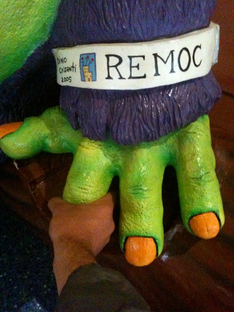
So I got back from Chicago on Monday, where I went to take care of this blighted piece of public art. “Remoc” is this big old green beast who I made with a sculptor buddy back in like 2005, at the behest of my old boss, for the UChicago Childrens’ Hospital. Theoretically he makes sick kids laugh. I’ve seen this. I know it happens sometimes. Usually when you pull his finger, as above. However it is hard not to see him as basically a monster whose job it is to complicate my life.
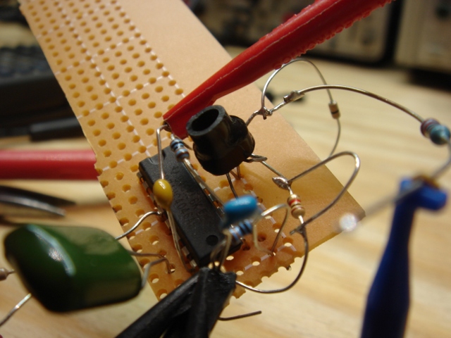
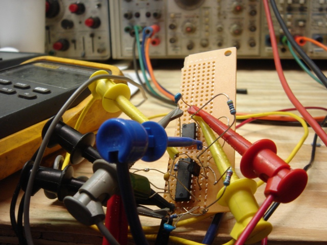
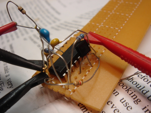
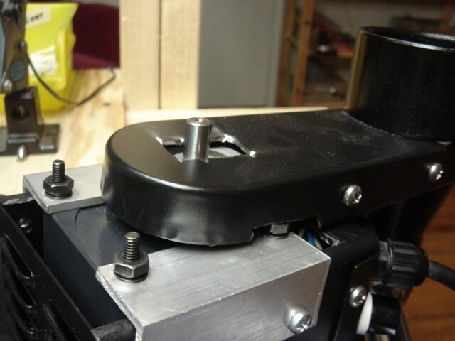
In some earlier posts I talk about some of the capacitive sensors I designed for him, to allow him to sense childrens’ touches. Well, they developed problems (spurious reads) and I had to head back to the midwest to have a look.
I knew his sensor circuits were pretty resolute, but I basically no-brainered his sensor code because I was too confident in my design. The day before I left to head back to the windy windy I re-wrote a bunch of his sensor handling code.
Mostly I changed how he crunches numbers. Sensor data ends up getting put into two different filters; one with a long time constant and one with a short one. His long term averages are generated by an IIR which divides by 8192, so it takes something like 73,000 readings to settle from 0 to 4096 (12-bit sensors). Sensors were updated in the main game loop, so the loop timing was “fast but indeterminite”. I’d have scoped it, if I had a scope and the hardware in the same place. In real life it took him five minutes or so to settle from any particularly messed up event (like unplugging a sensor).
The short term averages do the same thing over 32. I tried using an FIR (where you have an array and subtract an old member and add in a new one) for this but it ended up being more of a pain in the ass as I kept missing some stupid bug I was making where I wrote off the end of an array so I just made it an IIR since there were people watching and expecting results.
The two were then compared via percentage difference. I also changed the way his serial monitor worked to make it easier to see all this data change in realtime (I’ve gotten really into sending ANSI clear-screen escape sequences to xterm. It’s hood, but it works).
What I learned from this was two of his ten sensors (the copper tape parts, installed in his bowels a million years ago, and also set on fire once or twice by the sculptor) have shifted positions — I could see this by looking at the readings and moving my hand around. So there was no fixing this (correctly) without cutting a lot of fiberglass. I asked the hospital folks whether they would be OK with cutting his arm off for a little while and surprisingly they said no. Which was just fine with me. I did what I could with the data coming out but it wasn’t much. You may have to womp on his cast really hard to trigger it now, but it won’t read spuriously.
While sensor-sensor interference may be a little bit of a problem, I could also could tell that there were bigger EMI problems, generated by switching the LEDs and PWM audio. Those sensors are relatively insensitive to LF noise, but not so much to HF, which I’d change in future sensor designs. For the nonce I changed when the sensors were polled in the game code and disregarded reads which happened during electrically noisy events.
You know, regular electronics stuff:-)
I’d love a chance to do him all over again, but until then, I’m _almost_ happy with how he is.
Here’s some of the code I used.
The following updates his averages/filters:
static void UpdateTouchsensorAverages()
// Work averaging magic on sensor readings.
// Capacitance is indicated by low readings.  When the readings increase it means a removed hand OR a temperature rise.
{
	unsigned int
		temp,
		i;

	for(i=0;i<NUM_SENSORS;i++)
	{
		temp=adcResults[i];

		// Update long term reading
		sensorLongTermAverages[i]-=(sensorLongTermAverages[i]/LONG_TERM_AVG_DIVISOR);		// Remove a chunk of the average.
		sensorLongTermAverages[i]+=temp;													// Add in our new sample into average.

		sensorShortTermAverages[i]-=(sensorShortTermAverages[i]/SHORT_TERM_AVG_ARRAY_SIZE);
		sensorShortTermAverages[i]+=temp;
	}
}
This next bit compares the two values and decides whether he is “touched”:
static unsigned int TouchsensorsToKeyStates()
// Take the touchsensor readings, look at thresholds, and make them into keypresses.
// Since there are no real keys in this application, this is straightforward.
// We will just pass this directly to keyStates.
{
	unsigned int
		i,
		tempMask;

	tempMask=0;									// Zero out "keys".

	for(i=0;i<NUM_SENSORS;i++)					// Make keys that correspond to all sensors.
	{
		if((sensorShortTermAverages[i]*SHORT_TERM_MULTIPLIER)+((sensorLongTermAverages[i]*sensorThresholdPercentage[i])/100)<=sensorLongTermAverages[i])		// Scale up the short term reading, add it to a determined percentage of the long term.  If the sum is less than the long term average, call it a touch.
		{
//			printf("TOUCH: %d\n",i);
			tempMask|=(1<<i);													// Mark this sensor as a pressed key.
		}
	}

	return(tempMask);
}
and this last part spits out RS232 data when I tell it to so I can “see what he’s feeling” like a marriage counselor:
static void DisplayAdcValues(void)
// Monitors Adc Shizz.  Prints out variables and touch info.
{
	unsigned int
		i;
	unsigned char
		inputChar;

	if(CheckTimer(TIMER_1))
	{
		ResetTimer(TIMER_1);

		SerialWriteByte(DEBUG_UART,'\e');	// ANSI clear screen.  Old skool!
		SerialWriteByte(DEBUG_UART,'[');
		SerialWriteByte(DEBUG_UART,'2');
		SerialWriteByte(DEBUG_UART,'J');

		printf("x to Exit\n");

		for(i=0;i<NUM_SENSORS;i++)
		{
			printf("S:#%d adc=%d L=%d S=%d DP= ",i,adcResults[i],sensorLongTermAverages[i],(sensorShortTermAverages[i]*SHORT_TERM_MULTIPLIER));	// Print the sensor number and its averages.

			if(sensorLongTermAverages[i]>(sensorShortTermAverages[i]*SHORT_TERM_MULTIPLIER))	// FIR is less than the IIR (this is how it should be when touched)
			{
				printf("-");
				printf("%d",((sensorLongTermAverages[i]-(sensorShortTermAverages[i]*SHORT_TERM_MULTIPLIER))*100)/sensorLongTermAverages[i]);	// Print percent difference the short term is from the long
			}
			else	// FIR is greater.
			{
				printf("+");
				printf("%d",(((sensorShortTermAverages[i]*SHORT_TERM_MULTIPLIER)-sensorLongTermAverages[i])*100)/sensorLongTermAverages[i]);	// Print percent difference the short term is from the long
			}

			if(keyState&(1<<i))	// Touched?
			{
				printf(" ***\n");
			}
			else
			{
				printf("\n");
			}
		}

		printf("\n");
	}
	else if(SerialRxBytesWaiting(DEBUG_UART))		// Something in the buffer?
	{
		inputChar=SerialReadByte(DEBUG_UART);	// Get it.

		if(inputChar=='x')
		{
			printf("\nMonitor Done.  Hope you learned something.  Bye!\n");
			SetGameState(RemocTerminal);
			gameSubState=GSS_0;
		}
	}
}
This is all C code (duh) which is compiled with GCC for an M68k target.
In this case, as in so many when I am lost in the programming weeds, my buddy Todd Squires gave me tons of useful pointers.
It is also worth noting that a more positive analysis might paint Remoc as an excuse to spend a weekend in my old hometown drinking beer on the Metra tracks and eating the worlds finest tacos, which exist in Chicago, and which pretty much grow on trees.
xo
TMB