Posts Tagged ‘VCOs / VFCs’

Component Variation, Or, The Least Sexy Electronics Problem Evar

Thursday, July 7th, 2011

Analog is sexy, we all agree, right? Embedded systems on the other hand, are full of lots of unglamorous problems. Filesystems, say. Inherently un-sexy.

Yawnz

But I think component variation is maybe the best, most un-sexy problem there ever was. The unsexy cherry on the diet sundae. Like, you HAVE to solve it if you are making lots of something or that thing as a population will suck, even though the one on your bench always ruled.

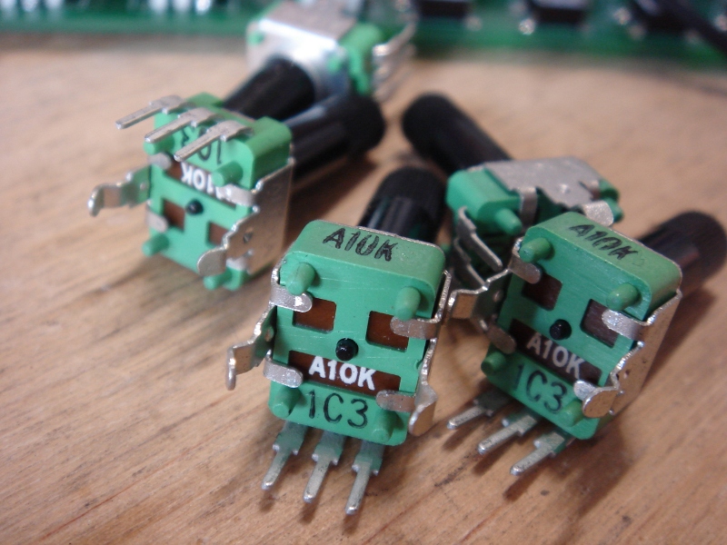
All the pots in WTPA2 are these custom Taiwan Alpha jobbies. There are two values, 10kA and 100kA. The VCO uses one of the 10kAs as a coarse control, and it sets the voltage into a current sink which in turn sets the frequency. I’d been messing with the op amps in this circuit to try and get some performance improvements and “all of a sudden” one of the DUTs didn’t work correctly. At first I figured it was the opamp change, but after a lot of measurement and desoldering and component testing, it turned out one of the 10k pots was really 11.4k. This was a greater than 10% variation!

I’d built a margin in for error, but this was above it, and the current sink was getting too high of a voltage. I tested a dozen pots or so from the bin, and all of them were much less off. Still, since one was off, probably another one could be as well. It could even have been a result of the soldering process. I actually bothered to do a DC simulation at this point (using qucs) and fiddled with the component values until they were all as off as I could imagine them possibly being, and then resized the scaling resistor that sets the upper range of the VCO. It was a really crappy annoying unsatisfying solution, because it means that MOST of the units will be operating at a slower maximum clock than they need to. But that one in twelve or one in 100 will work correctly. Serves me right for getting the cheap pots, but there you go. Margin. Component variation.

Least Sexy Problem Evar.

TB
WTPA2 Clock Characterization & Pulse Shaping

Wednesday, July 6th, 2011

So, after getting back to client work for a minute, I decided to try and nail the clock pulse shaping circuit problem with a more viable solution than throwing in an extra $5 op amp.
The problem with the original pulse shaper circuit was simply that it was designed with a function generator and not a 20 cent opamp in a RC oscillator. The idea was sound (I think) but the values were not.

The real problem is that the square-to-pulse converter has to shape two different clocks — it’s always driving the same IRQ pin, but it can be hooked up to WTPA2’s 4046 based VCO, or the LM358 based on a user switch. The 4046 is HC logic, and has really square edges. The LM358’s edges are not square, and their slew rate seems frequency dependent also. So, you could optimize components for one or the other, but not both. I did some bench tests to figure out what I needed to change to get this right.

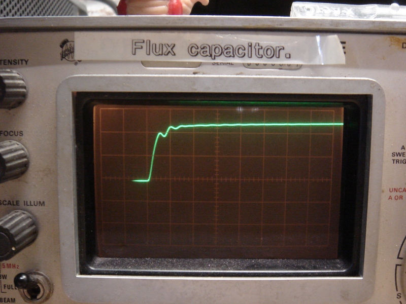
Check it. Here’s the rising edge of the output from the VCO:
4046_Edge

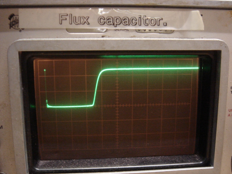
And the corresponding output from the pulse shaping network:
4046_pulse

Since we aren’t changing the VCO, this is what we’re gonna call “normal”. The top trace shows a risetime of about 0.1uS (scope is 0.1uS/div, 2v/div) which is quite fast (50V/uS in opamp terms). The ringing here probably has to do with the long ground connection on my probe, and it doesn’t hurt anything except my pride. The bottom trace (the output from the pulse shaper) shows a clean low pulse which is about 6uS long total (2uS/div)
Now, here’s the LM358:

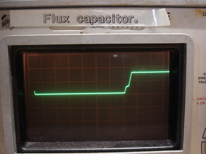
358_Edge

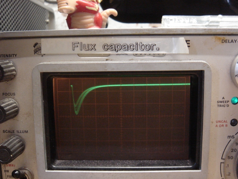
And the corresponding output from the pulse shaping network:
358_Pulse

Waaay different! This is the LM358 at its best incidentally — tested at low oscillator frequencies. At higher clock frequencies it slews even more slowly.
The top trace is 10uS/div, and shows a rise time of about 25uS (it’s 60uS with the clock cranked up to 25kHz). Annoyingly, it has that characteristic LM358 style crossover mess. AND it only gets up to about 4v. The rise time is really what matters though, and it is orders of magnitude slower than the 74hc4046. The bottom trace shows the output of the pulse shaper, trying but not quite making it. That dip never makes zero volts and might last 0.25uS. This doesn’t consistently trigger our interrupt-on-change IRQ.

So, the question was what to do. I tested a TLV2462 opamp (my goto op amp for embedded stuff, made by TI, a tank) and it performed equivalently to the 4046, and the pulses worked great. It’s slew rate was rated at 1.6V/uS, which is about 5 times faster than the LM358’s 0.3 V/uS. So it was faster, but not by orders of magnitude. If I could find an opamp which cost about the same as the LM358 and had a better slew rate, that seemed appealing rather than trying to hack up a circuit on 300 already-fabbed boards. The question was how fast we needed to go.

I settled on three opamps for the test: The Microchip MCP6002 (0.6V/us), the Microchip MCP602 (2.3V/uS) and the Texas Instruments TLC272 (5.3V/uS). A few days later I had them all from Digikey. I tested the MCP6002 first, since it was the cheapest. (0.27 at quantity, as opposed to the LM358’s 0.20) Surprise surprise! It worked great on the first try.
Although I didn’t measure the rise time, it looked clean on a scope. The ouptut from the pulse shaper was 6-7uS which is as good as (and more importantly in line with) the logic chip in the VCO. This was also consistent with the TLV2462.

In conclusion, the cheapest and easiest way to solve this problem is (I think) to eat 0.27 per kit and throw in another opamp. Further, the results are interesting because they show that above a certain rise time, performance remains the same. My guess is that there’s a knee point in that filter, and as long as the dominant frequency of the edge is above it, we’re good to go. In this case, a clean 0.6V/uS output was enough to trigger the shaper reliably.

Now that the results are consistent and I’m in tweak mode anyway, I’ll probably try and get those pulse times down by half or so, just in case the ISR gets faster.

Analog is fun, yo.
xoxox
TB

4046 VCO Final Breadboard Proto

Monday, June 28th, 2010

So this weekend marked the last screwing around (breadboarded, at least) with the VCO design for WTPA2. I knew that I could get the frequency range I needed out of a 4046 based VCO with a current sink in place of a frequency setting resistor but I was a little worried about temperature drift and very low frequency performance. Just for shits, I gave the circuit above a shot. It replaces the current sink with a standard two-transistor current mirror. The two devices above are crappily thermally coupled with a piece of heat shrink.

What I found with this is that temperature performance wasn’t too much better. It was still pretty easy to get this VCO to go crazy with the heat gun, although it was possible to get it to go crazy BI-DIRECTIONALLY based on the direction you were slathering on the sweat. Cute, but not useful.
One thing that WAS cool is that the current source compliance was great! The control voltage could get a lot higher than it could with the one-transistor sink before saturation, I assume because of the lack of emitter resistors in the circuit. Still, that was like a consolation prize.

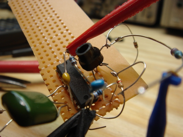
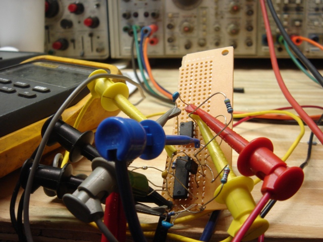
So I caved and built this:

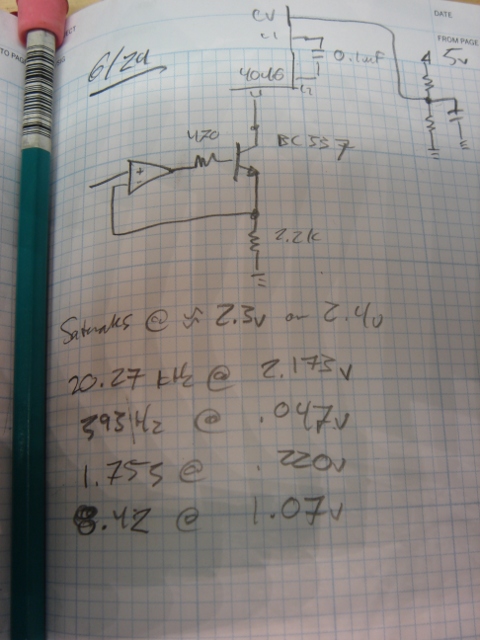
Here’s the schematic for it:

It’s what all the docs I saw suggested originally (a closed loop current sink where the op-amp compensated the temp drift of the transistor) and it totally works and does what it’s supposed to. The only annoying thing is that at VERY low currents the device is non-linear, but what are you gonna do. At a hundred Hz sampling rate all samples sound like farts anyway.

The CV has to be kept below about 2.2v to keep the transistor from saturating (the VCO goes nuts when this happens) but you can fix this with a divider on the input. The range with these components is about 0-20kHz with a CV from 0 to 2.1v or so.

Now I gotta figure out what to do with that other half of the 358. I sort of don’t want to pass it audio, because it’s a recipe for coupling noise into the circuit. We’ll see….

This week I’m working on the board layout for the first WTPA2 revision. I expect the next post here will be about that.
xo
TB

WTPA2 4046-based V-to-F Circuit, take 2

Saturday, June 12th, 2010

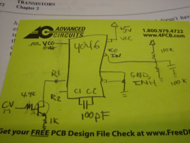
Boom! Current sinks all the way:

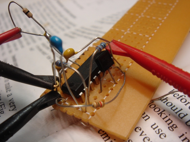
Because I am late to a BBQ I will not bother here to kick on the corporate dog and grumble about how not a single Rat Shack in downtown Brooklyn sells solderless breadboards. I will however sing the praises of H&H (buy that book. I’m not kidding) and the value of the current sink in the previously discussed VCO clock circuit. I soldered this mess up on some perfboard and in short order had a VCO that happily went from DC to >> 1MHz! The linearity is TERRIBLE, but it proves that the range is there. I’m pretty sure I can fix it adequately for my needs with just fiddling with the passive components in this circuit. Hopefully. Here’s the schematic, captured in time honored analog fashion:

Those component values are way stupid, but I think this is the topology. I may yet get away without the op-amp. Live and learn. And happy BBQing.
xo
TMB

WTPA2, Current Sinks, and the 74HC4046

Wednesday, June 9th, 2010

So once again somebody on the forum came through and found this guy’s page about designing a switched capacitor filter, where he talks about using a CURRENT SOURCE (sink, actually) instead of a resistor on one of the 4046’s frequency setting pins. This was a real forehead smacker. Thanks Kyle (erschlagener) for the heads up, and thanks to Tim for putting that out there in the first place!

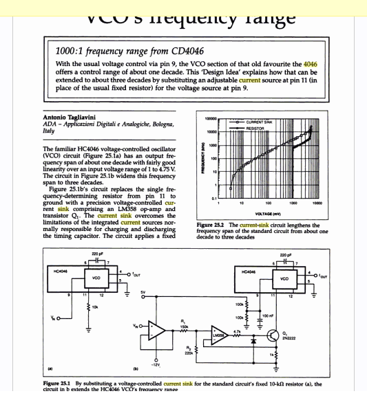
Requisite googling found an EDN note about this, too:

Which claims a 1000:1 frequency range out of the 4046’s VCO!
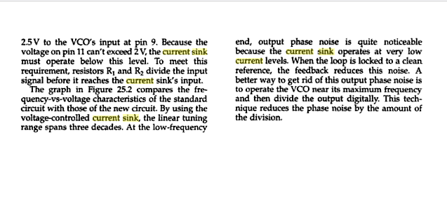
It also confirms what I’d found on the breadboard before, namely that the 4046’s frequency output is not particularly linear outside of about 1v-4.75v, and that inside there you can expect to get about a decade of range. So I felt less dumb.

This note also has the bright idea of putting the sink in the feedback loop of an opamp, which almost certainly helps linearize the sink’s behavior at low voltages by getting rid of base current related weirdness.

Enter a quick trip to findchips for some pricing data. Turns out that the 4046 and a transistor are certainly cheaper than the LM331, although they take up more real estate. Even throwing in an cheap LM358 still costs less than the LM331, although the savings start to get less significant. Now, if there was some good use for that second op-amp in a ‘358, that’d be something…

This recalls some quote I heard and want to attribute to Jim Williams, though I can’t recall exactly where it’s from, about how in modern circuits like 80% of the thing is digital and takes 20% of the time to design, whereas the 20% that’s analog takes the 80%. Sometimes it does seem true, although it might just be (for me anyway) that the analog parts are a lot of fun :-)

Back to the breadboard!
xo
TMB