Posts Tagged ‘WTPA’

4046 VCO Final Breadboard Proto

Monday, June 28th, 2010

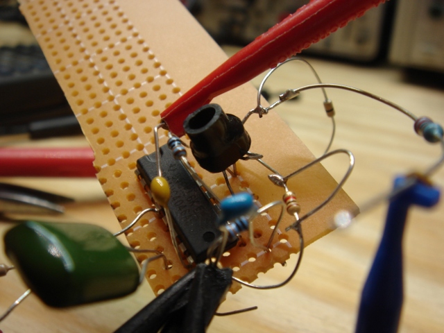
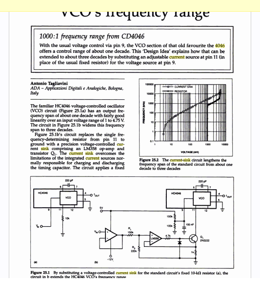
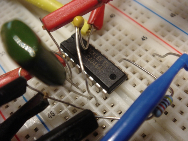
So this weekend marked the last screwing around (breadboarded, at least) with the VCO design for WTPA2. I knew that I could get the frequency range I needed out of a 4046 based VCO with a current sink in place of a frequency setting resistor but I was a little worried about temperature drift and very low frequency performance. Just for shits, I gave the circuit above a shot. It replaces the current sink with a standard two-transistor current mirror. The two devices above are crappily thermally coupled with a piece of heat shrink.

What I found with this is that temperature performance wasn’t too much better. It was still pretty easy to get this VCO to go crazy with the heat gun, although it was possible to get it to go crazy BI-DIRECTIONALLY based on the direction you were slathering on the sweat. Cute, but not useful.
One thing that WAS cool is that the current source compliance was great! The control voltage could get a lot higher than it could with the one-transistor sink before saturation, I assume because of the lack of emitter resistors in the circuit. Still, that was like a consolation prize.

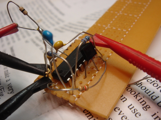
So I caved and built this:

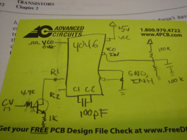
Here’s the schematic for it:

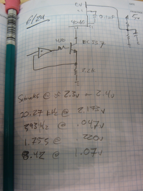
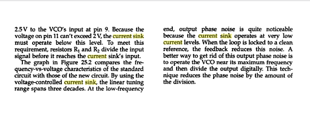
It’s what all the docs I saw suggested originally (a closed loop current sink where the op-amp compensated the temp drift of the transistor) and it totally works and does what it’s supposed to. The only annoying thing is that at VERY low currents the device is non-linear, but what are you gonna do. At a hundred Hz sampling rate all samples sound like farts anyway.

The CV has to be kept below about 2.2v to keep the transistor from saturating (the VCO goes nuts when this happens) but you can fix this with a divider on the input. The range with these components is about 0-20kHz with a CV from 0 to 2.1v or so.

Now I gotta figure out what to do with that other half of the 358. I sort of don’t want to pass it audio, because it’s a recipe for coupling noise into the circuit. We’ll see….

This week I’m working on the board layout for the first WTPA2 revision. I expect the next post here will be about that.
xo
TB

WTPA2 4046-based V-to-F Circuit, take 2

Saturday, June 12th, 2010

Boom! Current sinks all the way:

Because I am late to a BBQ I will not bother here to kick on the corporate dog and grumble about how not a single Rat Shack in downtown Brooklyn sells solderless breadboards. I will however sing the praises of H&H (buy that book. I’m not kidding) and the value of the current sink in the previously discussed VCO clock circuit. I soldered this mess up on some perfboard and in short order had a VCO that happily went from DC to >> 1MHz! The linearity is TERRIBLE, but it proves that the range is there. I’m pretty sure I can fix it adequately for my needs with just fiddling with the passive components in this circuit. Hopefully. Here’s the schematic, captured in time honored analog fashion:

Those component values are way stupid, but I think this is the topology. I may yet get away without the op-amp. Live and learn. And happy BBQing.
xo
TMB

WTPA2, Current Sinks, and the 74HC4046

Wednesday, June 9th, 2010

So once again somebody on the forum came through and found this guy’s page about designing a switched capacitor filter, where he talks about using a CURRENT SOURCE (sink, actually) instead of a resistor on one of the 4046’s frequency setting pins. This was a real forehead smacker. Thanks Kyle (erschlagener) for the heads up, and thanks to Tim for putting that out there in the first place!

Requisite googling found an EDN note about this, too:

Which claims a 1000:1 frequency range out of the 4046’s VCO!
It also confirms what I’d found on the breadboard before, namely that the 4046’s frequency output is not particularly linear outside of about 1v-4.75v, and that inside there you can expect to get about a decade of range. So I felt less dumb.

This note also has the bright idea of putting the sink in the feedback loop of an opamp, which almost certainly helps linearize the sink’s behavior at low voltages by getting rid of base current related weirdness.

Enter a quick trip to findchips for some pricing data. Turns out that the 4046 and a transistor are certainly cheaper than the LM331, although they take up more real estate. Even throwing in an cheap LM358 still costs less than the LM331, although the savings start to get less significant. Now, if there was some good use for that second op-amp in a ‘358, that’d be something…

This recalls some quote I heard and want to attribute to Jim Williams, though I can’t recall exactly where it’s from, about how in modern circuits like 80% of the thing is digital and takes 20% of the time to design, whereas the 20% that’s analog takes the 80%. Sometimes it does seem true, although it might just be (for me anyway) that the analog parts are a lot of fun :-)

Back to the breadboard!
xo
TMB

WTPA2 Initial Hardware Release Announced! With a Pretty Case, too.

Monday, May 31st, 2010

First beta WTPA 2 release date got announced on the Narrat1ve Forum today. I promise to have pictures of a more-or-less-working printed circuit board HERE by July 1st. I’ve already got a rep at Future who I think can save me some dough in parts sourcing, which is good, and I’ve got initial hardware specs (RAM, rotary encoders, new MCU etc) done. The board is starting to come together too. Once all that happens the firmware will start to get changed and I’ll make sure the pretty case fits and looks nice.

WTPA2 Initial Clock Test

Friday, May 21st, 2010

Normally I hate solderless breadboards, but I was kindof inspired by doing recent work with Adafruit that they were OK for iterating through low frequency, proof-of-concepty kind of stuff.

And a good thing I was, too. WTPA2 was slated to have a VCO as a sample clock source, bringing that feature back from the murky WTPA v0.98 days. However, a standard 4046 clock had some troubles, at least as I breadboarded it.

Using a 5v supply, and a CV at the VCO input of 0-5v, and varying the values of the VCO resistors and caps I wasn’t able to get much better than a decade of frequency out of the part. I scribbled these numbers all down on various post-its that no longer make a lot of sense to me, but getting an FMax of 20KHz and an Fmin of <100Hz seemed pretty much impossible, both experimentally and once I bothered to do the math problems in the datasheet. Moreover (and I'd seen this before with the 4046 in video synth stuff) once the CV gets too close to 0v or too close to the positive rail, the oscillator tends to either stop or jump up in frequency. If you haven't already, it's worth referring to the 74HC4046 datasheet while reading this pontification, at the very least to convince yourself that I am not totally making this up.

This is not the most rigorous breakdown, I know, but it was enough to convince me that a standard 2 resistor, 1 cap, and and CV style 4046 VCO was not going to hack it without some kind of magic. I’d been curious about the LM331 V-to-F so I got its datasheet and did some more scratchpad math and convinced myself that it was a lot more likely to come close to what I wanted without serious massage. It’s quite a bit more expensive than the 4046, but at least it’s physically smaller.