WTPA2 Initial Clock Test
Normally I hate solderless breadboards, but I was kindof inspired by doing recent work with Adafruit that they were OK for iterating through low frequency, proof-of-concepty kind of stuff.
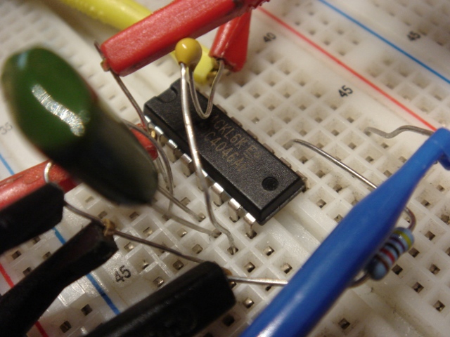
And a good thing I was, too. WTPA2 was slated to have a VCO as a sample clock source, bringing that feature back from the murky WTPA v0.98 days. However, a standard 4046 clock had some troubles, at least as I breadboarded it.
Using a 5v supply, and a CV at the VCO input of 0-5v, and varying the values of the VCO resistors and caps I wasn’t able to get much better than a decade of frequency out of the part. I scribbled these numbers all down on various post-its that no longer make a lot of sense to me, but getting an FMax of 20KHz and an Fmin of <100Hz seemed pretty much impossible, both experimentally and once I bothered to do the math problems in the datasheet. Moreover (and I'd seen this before with the 4046 in video synth stuff) once the CV gets too close to 0v or too close to the positive rail, the oscillator tends to either stop or jump up in frequency. If you haven't already, it's worth referring to the 74HC4046 datasheet while reading this pontification, at the very least to convince yourself that I am not totally making this up.
This is not the most rigorous breakdown, I know, but it was enough to convince me that a standard 2 resistor, 1 cap, and and CV style 4046 VCO was not going to hack it without some kind of magic. I’d been curious about the LM331 V-to-F so I got its datasheet and did some more scratchpad math and convinced myself that it was a lot more likely to come close to what I wanted without serious massage. It’s quite a bit more expensive than the 4046, but at least it’s physically smaller.
Tags: Analog, Device Characterization, Hardware, PLLs, VCOs / VFCs, WTPA, WTPA v2.0