Posts Tagged ‘WTPA v0.95’

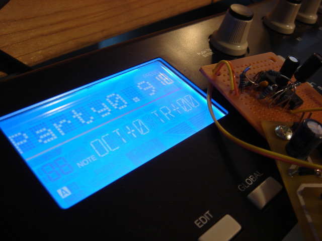
WTPA v0.95 ISR Speed Characterized, Code Revs, H/W Changes

Thursday, January 8th, 2009

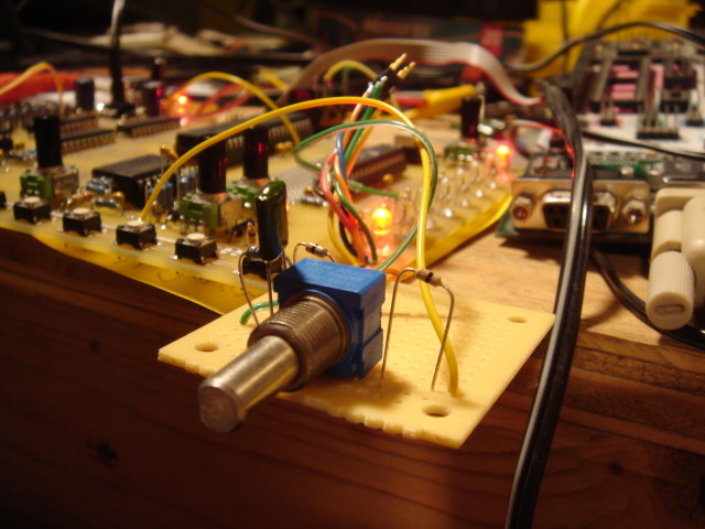
Online in 2k9, my ducks.

So sometimes, contrary to common blogline belief there are times when I’m quite busy even when I’m not posting. This New Year / Holiday period was one of them. There are some big advances on the WTPA front:

First, all circuits and modes are totally functional. The resampling problem I was having had two roots. First (and lesser of the two) the input impedance of the AVR’s A/D converter is actually a lot lower than I ever realized. In the datasheet Atmel recommends that you don’t drive the ADC with anything less than a 10k impedance but I actually found that an input resistance as small as 470 Ohms still
produced a noticeably smaller waveform at the ADC input pin than driving the pin directly from the output of an opamp. This was easy (though annoying) to fix — it requires another op-amp section and a redesign of the summing amp into the resampling ADC input. The only unfortunate thing about this is that it will drive the cost of the final device up for you, dear customer, and this kit is already, as they say in France, tres cher.
Still, I made a decision a long time ago that when I design things for me (as opposed to the toy world) I will always err on the side of badassery rather than cost, because I can. And because everybody wants to be a baller, right?

The other (more significant) problem was a Read-Modify-Write issue in the audio ISR. OMGWTFBBQ, was it hard to find! When is a NOP not just a NOP? When it lets you sync an output port you’ve just written to with its input latch. Weird, weird bugs from that one, to be sure. And fixing bugs in my code is, like, totally free!

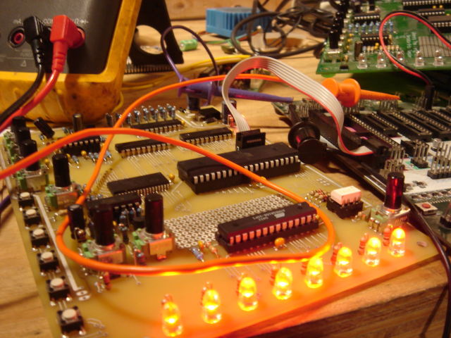
In other important news I bothered to scope out the speed of the audio IRQs and compare them to the old WTPA. As I had hoped, there was mondo improvement on that front:

  • WTPA 0.9, Time in IRQ:
    • Recording / Playback: 22-24uS
  • WTPA 0.95, Time in IRQ:
    • Recording: 5.8uS
    • Playback: 7.5uS
    • Resampling/Overdubbing: 9.0uS

This means that we could now sample at 44kHz (CD quality — remember CDs?) without breaking a sweat if we wanted to! Of course, I’m not sure how much good that would do us since the ADC on the AVR is already “not-so-accurate” at the paltry 24kHz I’ve got it set to now. But hey, the headroom is there if you all want to get your overclock on.
Practically this means that the processor now actually has some time to get some work done other than audio, which is good.

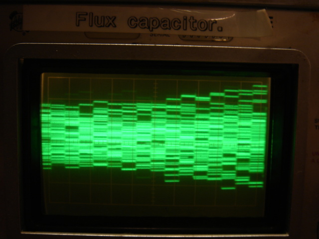
So the final hardware related issue in this animal is the jitter generator. The way it was originally designed the jitter generator used a PRBS white noise source to mess up the clock signal, and it worked! Sort of.
It became apparent that when the “jitter” control was at maximum, the knee frequency of the filter on the white noise became the dominant interrupt frequency. In English: The fastest noise waveform actually determined the clock frequency in a totally deterministic sounding way.
Since this frequency was different than the clock frequency, you would hear a “jump” in sample rates when adjusting the jitter. This sucked. Right now I’m trying to get the jitter to mess up clocks of all frequencies equally well without inserting a dominant frequency of its own. Meaning a jittered-up 600Hz clock will still have a frequency of 600Hz, it will simply have a totally random duty cycle. (You know, like peak-to-peak displacement, like Wikipedia says under “Jitter”).
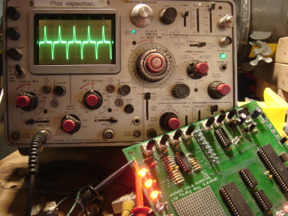
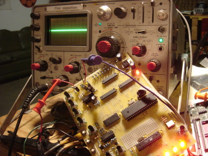
After fiddling around with another analog solution (pictured above) and then with some circuit sketches using AND gates and JK flipflops I realized that the best way to do this (everybody all together now) was IN SOFTWARE. I can’t decide if it’s sad or not that it always seems to be that way. Anyhoo, once I’m done with that it’s time for new boards.
Oh, and my birthday is coming up in a little less than a week. Send me naked pictures, or LOLCATs or something. Xoxoxox.

WTPA v0.95 Gets All MIDI Up In Here (and Hardware Changes)

Monday, December 22nd, 2008

As a matter of fact that IS an Akai MPK49 inquiring where the party is.

In brief: all the MIDI business is working great, although I’ve run into some annoying problems resampling (what guitar players might call overdubbing) which are both hard- and firmware related.
I’m late to haul my freight back to the mid-midwest for the holidays as of now, but you can see the hardware fix I did in the form of that gnarly looking perfboard. That part at least works great. Maybe I’ll nail the firmware issues over some wassail, Kwanzaa candles, or something. Happy Holidays!

WTPA v0.95 Sampling, Jittering

Tuesday, December 16th, 2008

WooHoo!

Today is momentous. It samples; from the shoulders of giants it does. I even made a snarled up little video of the first experiment in the act. Scandinavians vs. USA in the bass-less wastelands of Camcorder Flats. Or perhaps holding hands: Glasnost or whatever the equivalent is with stank cheese, progressive design, and socialized medicine.

I tell you, I am a sentimental mess like Lawrence Sterne never made. Honestly, when the first phrase of music kicked out of this thing I almost peed. And then I had a beer or two, which explains the tone here. However, I will stand by this: The New Version Sounds Great Or At Least Slays The Shit Out Of The Old One. I think this mostly has to do with the noise floor not gumming up the quiet parts and _maybe_ some improved amp design.
It’s not perfect by any stretch: I still haven’t hammered out anything in the way of new features, and it isn’t benchmarked yet (I’m very curious to see how much time it spends in the audio ISR) but it IS bumpin, and this test has been great fun. The jitter generator works and sounds weird in an exciting way BUT is tweaky and needs to be tuned in both the analog and firmware domains. I think it’s a keeper, though, just from the initial listening.
As I had hoped the noise floor is pretty good! It’s not annoying, or really even noticeable! I can still see some gnarls on the scope, though, and will hunt them to their holes and Make Reckoning. Like “Reckoning” was “Clean” or “All”.
AND there’s more than enough sample time to hang yourself with the new RAM. Booyah.
Next: MIDI, and ferreting out any remaining hardware bugs and revving the board to the FINAL VERSION!

WTPA v0.95 Noise Floor and Programming Victories

Wednesday, December 10th, 2008

Yesterday was a good day for sampler technology!


Three really important things got done; two are improvements on the old sampler:

First: the serial link between the MCUs is now totally robust and fast. As I suspected the real problem with the serial before was the internal RC oscillator on the helper MCU. For now it’s been replaced with a 7.3728MHz crystal, but Digikey just rolled up with some 18.432MHz crystals this morning which I’ll be using instead, I think (these particular and seemingly-weird frequencies are exact integer multiples of common UART frequencies, and allow 0 baud rate error).

There were a couple other little forehead-smacking moments where I got bit by casting errors and other general programming bugs but they weren’t really bad once the UART worked. Like for instance — if you declare a variable “theByte” as an unsigned char, set it equal to ~’p’, and then later check for equality with ~’p’, it comes back false. Know why? Know how to fix it? I do now. :-)

Second: It makes audio! Since I already put a picture of a noble sawtooth wave up a million years ago and since the old sampler definitely did this just fine, this is less exciting. BUT it does mean a couple things. The new DAC works, and the analog sections (mostly) work and all the volume pots are the right way around. The VCO works, and the jitter generator — Oh boy does it work! All these need tweaking but they’re all rocking solid.

Third: I spent a long long time fiddling with the PCB and tracking down noise demons. This, I am happy to say, was a big success and a _huge_ improvement on the old sampler!

Pictured above are some example waveforms. On the left is a picture of the output of the old sampler with the preamp gain, through level, DAC level, and master volume all the way up. You probably can’t read the V/div knob on the scope, but this waveform is unmistakably clock noise which has capacitively coupled into the audio path and has been amplified such that it is ~220mV at the output. Yikes! This is really bad. Those of you who’ve heard the original WTPA know that this whine is one of its not-so-good-akshully characteristics.

The photo on the right is a noise picture of the new sampler after a little screwing around by me. Under full-gain, worst-case noise conditions, the new sampler has approximately 4mV of clock feedthrough. This is 34.8dB of improvement!

There are a couple noise sources in the WTPA family. One source of LF noise is the LEDs pulling current spikes from the supply when they turn on. This is at its worst when running from a not-so-low impedance supply (like a 9v battery or worse an STK500 through the ISP header) and did manage to find its way into the audio but it wasn’t terrible. The best fix for it was to improve filtering at the op-amp reference terminals (the VDD/2 level at the non-inverting terminal of a summing amp, say) since the noise that got there got amplified by the circuit’s gain. This helped for sure.

By far the worst noise source is clock bleedthrough, although the new design also shows bleedthrough from the white-noise generator. Improving this was a little trickier. A couple things made a big difference. Varying the gain on the preamp as opposed to keeping the gain fixed (and high) and attenuating its input level was one. Re-doing the design with better ground and signal routing mattered A LOT, although I still had to rip up a trace with an exacto — one poorly-thought out connection added nearly 100mV to the output noise here. Filtering the analog references better helped deal with this noise a little, too.

Finally, I think a ground plane (or two) are in order for the final hardware revision. I also think associating the VCO and Jitter Generator with the digital supply lines (or at least isolating them from the quiet amplifier analog supply) would be a really good idea. I might even use a choke input to the quiet analog supply. We’ll see. Either way, this statistic is already A LOT better than it was, and I’m excited.

Next: Sampling / RAM / throughput rate test, and more fun analog tweaking.

WTPA v0.95 Gremlins

Saturday, December 6th, 2008

The lone and level sands stretch far away from this nasty Nas, I’m afraid:

Not that you can tell from gazing on this benighted silicon Ozymandias, but no pretty waveforms will happen tonight. It’s not a total loss; there’s some badassery that came through and TON of code, but since I said I’d post today here’s the breakdown:

The body of the code is done for both MCUs, at least at first blush, and the ISRs are now based on the parallel interfaces. The LEDs look crazy hot. Messy little resistors and whatnot are dutifully appearing on the board. The square waves are almost square.

The bad news is that all the old timers who I didn’t pay attention to were right — UART communication on internal RC oscillators is dodgy at best. The real (and unforseen) challenge of the last 16 hours has been massaging the serial link between the two MCUs enough that it works. It limps along now but it sucks. My studied conclusion is that the second MCU really needs its own crystal, and it might as well be at a UART-friendly frequency.
I probably have some laying around somewhere, and will dig them (and exacto blades) out this weekend.

Other fun bugs and riders of the nitpick train include:

The AVR toolchain doesn’t seem to be very excited about the 48p/88p/168p MCUs, and although you can fool it, doing so raises the “bad idea” error flag. Further, the STK500 seems to only want to program the old-ass m168s I dug out to rectify this problem ONE TIME, before getting totally weird. This is a good one: These parts are socketed in the STK, mind, and the fuse bits remain totally unchanged through this whole process. You put code onto the part just fine and boom, it becomes unprogrammable. I did this THREE times. Furthermore, reading the Vtarg on the STK500 shows 6+ Volts, and the device times out when you try to communicate with it. Say what?
I started shopping for a new STK, until further fiddling revealed you can a.) physically pull the RESET pin to ground on the socketed target device using an alligator clip (or stream of foul language) which allows it program just fine OR you can socket and connect to another WORKING part, and move the Vtarg down to 3v, whereupon the old “broken” part works just fine again. Gremlin central.

Writing the code was, thankfully, pretty straightforward and I discovered a kickass feature in avr-libc: ISR_ALIASOF() — this reduced the accumulated ISR code to half the size — thus doubling its beauty.
Finally, a point of consideration: Naming an electonic device on your website “Where’s The Party At” makes for no small amount of schoolgirlish giggling when looking at your keyword referrals in Google Analytics. In keeping, I have decided to name my next piece “Hot Hipster Tang For Altbros”.