Posts Tagged ‘Hardware’

Vectors, or “My Man Inf Left A VEC and a 9 At My Crib”

Thursday, August 8th, 2013

So awhile back my man Andrew Reitano dragged home a vector monitor from an old Asteroids arcade cabinet.
Here’s what we’ve done with it so far:

It was a long road to get there!
For those of you born after the cold war, Asteroids was a hugely popular game by Atari which used a now-obsolete style of monitor. If you haven’t played one in an arcade you owe it to yourself to do it, because they look like nothing else. The phosphor artifacts are trippy and beautiful.

Anyway, the trick with these things is that they get driven more like an oscilloscope than like a normal TV or raster monitor. Meaning, you send them voltages and deflect an electron gun to a certain spot on the screen, rather than drawing an image out line by line like an NTSC or RGB display. This presents all kinds of problems.

First, you have to move this electron gun at an even rate, and you need to do it on a halfway stable and reasonably fast way. I think Asteroids drew at 4MHz, meaning you needed to be pushing the gun that often AND slewing a beam that fast. After blowing up a handful of output transistors in the monitor, we came up with these:

VEC9_FPGA_and_Amp_small

That’s a Xilinx Spartan-3E FPGA on a Nexys2 dev board which Andrew programmed to be our vector generator, and a DAC/Amplifier board I designed to sling the beam around at 20 MHz and 12-bit resolution. First thing we did (this was with some gnarly R2R dac) was get a cube to display on the scope (I think the monitor was still fried from earlier “tests”). It kinda sucked:

Vec_test_05_small

Encouraged, we got drunk, fixed the monitor, Andrew wrote a rasterizer and we put the patron saint of Bed Stuy on the screen. It sucked less:

Vec_test_02_small

By then we were pretty sure we had a new arcade game in the works and the heavy lifting started. Andrew tuned the hell out of the VHDL and got the FPGA tweaking all kinds of gun parameters. I fixed the amp a couple times to get it running that gun right, and both of us spent a lot of time coding in C. I’ve wanted to make video games ever since I was a kid, but somehow this was my first foray into coding 3d rotations, particles, dynamic memory, and a lot of other generally non-embedded stuff. It ruled. We got to the point where we could rudely waste 3d polygons:

VEC9_Screenshot_Jul25_small

We wrote a storyboard about the Soviet Union blowing up Chicago, threw in a bangin track by Nicholas “Windbreaker” Read and coded a chaingun. Lastly, one awesome thing is that since we’d basically made a vector “video card”, it was not too hard to generate a commlink / stores display / HUD using a monochrome VGA display, running as a secondary monitor. It looks amazing!

We’re pretty sure we’re on our way to a totally kickass arcade cabinet once we get the real game coded. If you know what we should do with this hot mess once we’re done, hit us up!
TB, August 2013

BLDCs, the Wrong Way

Thursday, May 3rd, 2012

Hall Sensor Boo Boo
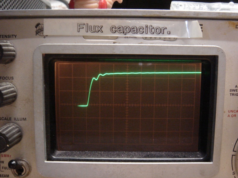
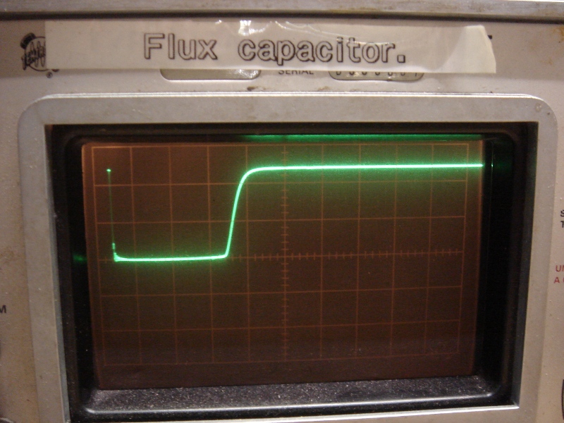
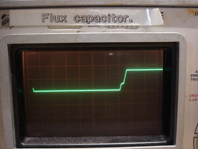
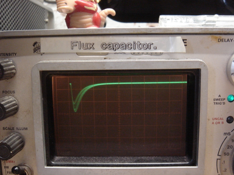
The above is a set of scope traces from the three coils of a BLDC which is being commutated incorrectly. Read on.

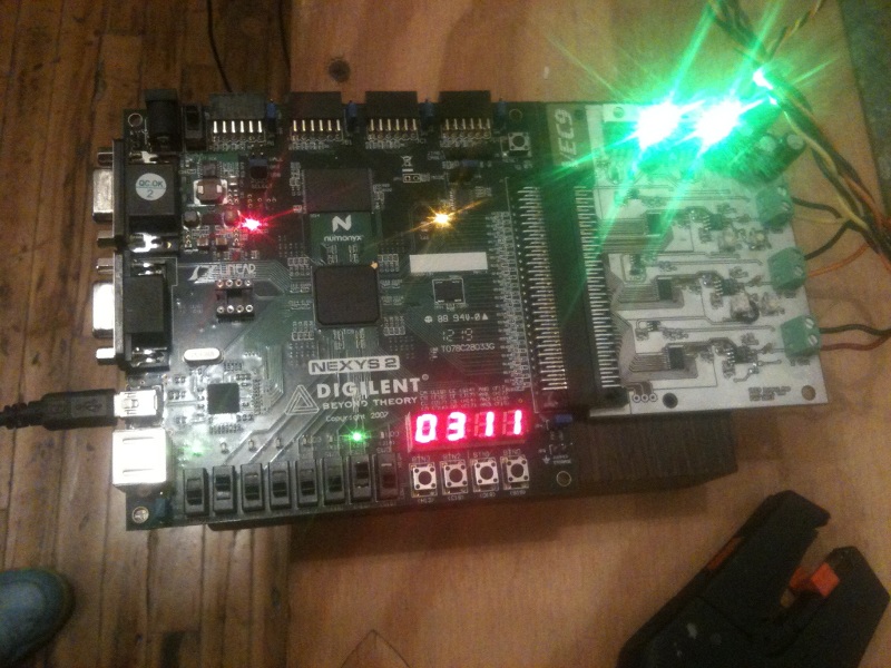
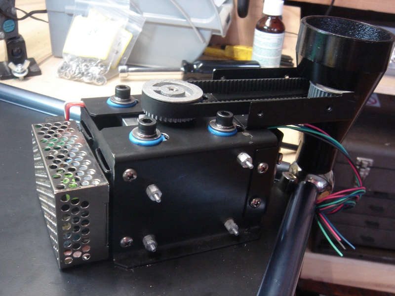
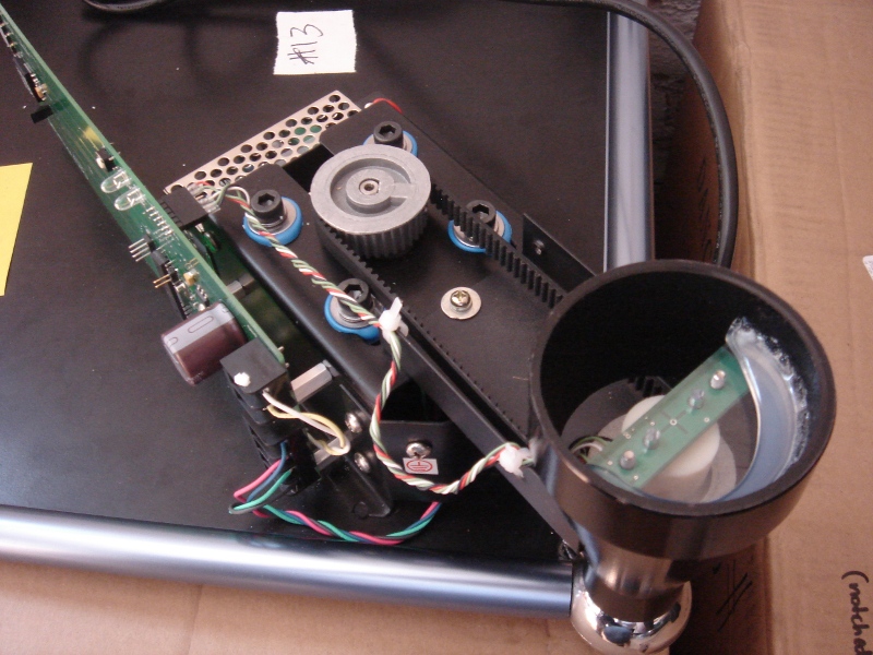
The job that’s been paying my bills and keeping me away from artsy-fartsy circuits for the past six months involves making a set of these enormous robot doors for a Certain Very Fancy Person’s house. Each door is 13 feet tall, around 7 feet wide, and weighs 1500 pounds. There are 66 of them in said house, and more in the servant quarters(!?!). The circuits on board each door have to handle running an onboard air compressor (which regulates a pneumatic weatherseal) as well as keeping track of temperature to linearize the pressure sensors when the weather gets cold. They also have to charge and maintain sealed lead acid batteries. They have commutated power rails. They have to communicate over said power rails, and do so using an capacitively-coupled data slicer and a proprietary protocol I wrote. This protocol has to be robust enough to bootload the processor over. It’s a proper embedded systems job.

All this having been said, the great majority of the real estate on the PCB is dedicated to running the big BLDCs that make the doors move. This post is some observations particulars of said motors.

I’d run lots of standard DC motors in past, and built H-bridges galore, but this was my first encounter with BLDC driving. As such, I made some mistakes in the prototype. And I am going to lay those out for you, dear reader, such that you might learn from the fires of MY workbench.

The motors in question were Maxon EC-Max 30 series motors with a gearhead. They are small, powerful, and expensive. We decided to use BLDCs for this job primarily because of their size, but the fact that the reliability is generally greater (no brushes) than a standard brushed motor certainly was a bonus. The BLDC driver circuit needed to fit into the stile of this door, which was only 1.5″ wide or so. The motors could be expected to stall under certain conditions, so the motor drivers had to be more Conan than not.

Once that driver was designed and fabbed, the fun on the workbench began.

A quick BLDC review:
Brushless DC Motors are like normal DC motors — except the user has to handle commutating the motor on their own. This means, more or less, wrangling the electric fields in the motor at the right time such that the motor turns. A standard DC motor has a set of “brushes” (usually pieces of carbon) that squeeze against the moving part of the motor (the rotor). These are responsible for getting power from stationary part into the spinning part. As the rotor turns, the brush presses on the correct bit of the rotor to get the fields doing their thing. This is cool because it’s easy to drive and relatively simple mechanically. The BAD thing about it is that the graphite/carbon brush wears down over time, AND the brush-scrape nature of the contact makes a world of tiny electrical arcs inside the motor which look cool but kick off a ton of electrical noise (and audio noise, which in this case mattered).
In a BLDC, it’s YOUR job to energize a set of coils at the right time to keep the motor turning. There are three (usually) coils in the stationary part of a BLDC and a number of magnets in the rotor. The trick is to energize the right combination of coils such that you pull the right magnet to the right spot at the right time. If you do this, the motor turns smoothly. It’s a sort-of-not-really like timing a spark plug, if you’ve ever had to do that.
The trick is, you need to know WHERE the rotor is at any given time, such that you can know when to turn off the last set of coils and turn on the next set. There are lots of ways to do this, but a common one is with hall sensors which read the rotation of the motor shaft via some magnets on that shaft. These are usually conveniently built into the motor. In my case, they read with 60 degree resolution, which is plenty to keep the motor moving correctly. Often, either a piece of hardware or an ISR reads the hall sensors, and then energizes the correct coils. This whole process can be as simple as a look up table.

There are lots of documents on the internet about BLDCs, but there are relatively few about what happens with incorrect commutation. The interesting part is when you mess it up and try to figure out what went wrong.

First step, the datasheet: The Maxon datasheet more or less recommends that you buy the Maxon motor drivers and just be done with it. Our form factor, target budget, and my not-insignificant sense of pride ruled that out. It DOES have a commutation chart, but it’s pictorial and is not that clear about “active high / active low” and other minor details like that. So, I made some guesses and let her rip.

In the course of letting her rip, I saw all kinds of exciting (read: trainwreck) motor beahvior. I figured out how that Maxon ran, but I also made a handy set of rules of thumb about what BLDCs do when you drive them wrong. From this, I made some procedures with which I ought to be able to start out with any unknown three-phase BLDC with hall sensors and derive how to get the correct drive sequencing. It’s like this:

Observations:

1.) BLDCs _WILL_ turn with some combinations of incorrect drive. This can mislead the un-wary.

2.) BLDCs usually not turn if the commutation sequence is mixed up. I assumed this would always be the case. It isn’t.
When a BLDC has a commutation sequence which is out of order, usually you see it STOP at some position and lock up, drawing stall current. If you aren’t on a current limited supply, or your motor drivers are not like Conan, you may damage your drive section. This is because whatever coil you’ve energized is pulling the BLDC to the wrong place and then KEEPING it there, since another set of halls has not been triggered. This probably means you have your driving steps out of order (or are energizing the wrong combination of coils).

3.) The interesting part — the BLDC _WILL_ spin, maybe, if you have the commutation sequence right BUT offset from the hall sensors readings. Meaning, if you are always energizing your coils one step ahead of where they should be, the BLDC will pull the motor to the right spot, but it will draw a lot of power doing it AND you will not have very much torque. If this happens, you probably have your hall sequence right AND your commutation sequence right, BUT they are lined up incorrectly.

Corollary:

1.) If you aren’t sure what your hall sequence is, you can spin the motor with your fingers (or a wrench, or whatever) and read the correct order of hall transitions.
2.) If you aren’t sure what your commutation sequence is, you can try messing with the order of different valid coil combinations and running your motor OPEN LOOP. This means stepping through your coil combinations on a timer, energizing them, and seeing if the motor turns. It will turn with bad efficiency again, and probably draw a lot of current, but it will turn when you have the sequence right. Best to do this on a current limited supply.
3.) Once you have those two pieces of information, you can line them up and figure out the correct drive sequence. This sequence will be the one in which the motor spins with the greatest torque and the best efficiency in both directions (IE, it has to work when reversed, too).

An unexpected benefit of doing this is that you see all kinds of BLDC commutation problems. This is useful when you’re debugging a system later, and have to deal with broken wires or damaged drivers, and can guess symptoms much more easily.

WTPA2 Clock Characterization & Pulse Shaping

Wednesday, July 6th, 2011

So, after getting back to client work for a minute, I decided to try and nail the clock pulse shaping circuit problem with a more viable solution than throwing in an extra $5 op amp.
The problem with the original pulse shaper circuit was simply that it was designed with a function generator and not a 20 cent opamp in a RC oscillator. The idea was sound (I think) but the values were not.

The real problem is that the square-to-pulse converter has to shape two different clocks — it’s always driving the same IRQ pin, but it can be hooked up to WTPA2’s 4046 based VCO, or the LM358 based on a user switch. The 4046 is HC logic, and has really square edges. The LM358’s edges are not square, and their slew rate seems frequency dependent also. So, you could optimize components for one or the other, but not both. I did some bench tests to figure out what I needed to change to get this right.

Check it. Here’s the rising edge of the output from the VCO:
4046_Edge

And the corresponding output from the pulse shaping network:
4046_pulse

Since we aren’t changing the VCO, this is what we’re gonna call “normal”. The top trace shows a risetime of about 0.1uS (scope is 0.1uS/div, 2v/div) which is quite fast (50V/uS in opamp terms). The ringing here probably has to do with the long ground connection on my probe, and it doesn’t hurt anything except my pride. The bottom trace (the output from the pulse shaper) shows a clean low pulse which is about 6uS long total (2uS/div)
Now, here’s the LM358:

358_Edge

And the corresponding output from the pulse shaping network:
358_Pulse

Waaay different! This is the LM358 at its best incidentally — tested at low oscillator frequencies. At higher clock frequencies it slews even more slowly.
The top trace is 10uS/div, and shows a rise time of about 25uS (it’s 60uS with the clock cranked up to 25kHz). Annoyingly, it has that characteristic LM358 style crossover mess. AND it only gets up to about 4v. The rise time is really what matters though, and it is orders of magnitude slower than the 74hc4046. The bottom trace shows the output of the pulse shaper, trying but not quite making it. That dip never makes zero volts and might last 0.25uS. This doesn’t consistently trigger our interrupt-on-change IRQ.

So, the question was what to do. I tested a TLV2462 opamp (my goto op amp for embedded stuff, made by TI, a tank) and it performed equivalently to the 4046, and the pulses worked great. It’s slew rate was rated at 1.6V/uS, which is about 5 times faster than the LM358’s 0.3 V/uS. So it was faster, but not by orders of magnitude. If I could find an opamp which cost about the same as the LM358 and had a better slew rate, that seemed appealing rather than trying to hack up a circuit on 300 already-fabbed boards. The question was how fast we needed to go.

I settled on three opamps for the test: The Microchip MCP6002 (0.6V/us), the Microchip MCP602 (2.3V/uS) and the Texas Instruments TLC272 (5.3V/uS). A few days later I had them all from Digikey. I tested the MCP6002 first, since it was the cheapest. (0.27 at quantity, as opposed to the LM358’s 0.20) Surprise surprise! It worked great on the first try.
Although I didn’t measure the rise time, it looked clean on a scope. The ouptut from the pulse shaper was 6-7uS which is as good as (and more importantly in line with) the logic chip in the VCO. This was also consistent with the TLV2462.

In conclusion, the cheapest and easiest way to solve this problem is (I think) to eat 0.27 per kit and throw in another opamp. Further, the results are interesting because they show that above a certain rise time, performance remains the same. My guess is that there’s a knee point in that filter, and as long as the dominant frequency of the edge is above it, we’re good to go. In this case, a clean 0.6V/uS output was enough to trigger the shaper reliably.

Now that the results are consistent and I’m in tweak mode anyway, I’ll probably try and get those pulse times down by half or so, just in case the ISR gets faster.

Analog is fun, yo.
xoxox
TB

WTPA2 Work Resumed!!

Monday, May 23rd, 2011

All right, so now that Cory’s biz is done and the art world is safe again, I can get back to God’s Work, by which I mean making samples that sound like farts. That’s right, WTPA2!
WTPA2 has been promised now for like a million years. I’m shooting for actually having it ready by the end of June for Bent Festival.

In that spirit, I dug out my old prototype. There’s a lot wrong with it. I found most of the hardware bugs way back when, and I added another input for a separate pitch control to the second sample bank. The idea was to use the spare op-amp to make an RC oscillator and use it to clock the second sample bank and use the main oscillator to clock the first bank. Clock sources could then be switched or interchanged in hard or software.

Problem is, the only uncommitted pins left that can trigger an IRQ are interrupt-on-change pins. That means that I can’t only trigger on a rising or falling edge — the ISR will trigger on BOTH. That means a 10kHz square wave will trigger 20k interrupts a second. I could make the clock half as fast I guess, but that seems like it will confuse people. For the time being I dealt with it by checking the state of the pin in the ISR, but that’s lame too. It means we vector away from mainline code twice as often as we need to. So I came up with this:

Analog Wyzyrdry

It’s a pulse shaper. It takes a clock input, and regardless of duty cycle, spits out a low-going pulse on every rising clock edge. The diode and cap here are responsible for separating out the edges, and the transistor squares them up again (more or less). Hooked up to the function generator (Agilent 33120A, 50ohm out) I can get a nice 0.5uS low going pulse really consistently! I can use this to trigger an interrupt, and the pulse will ALWAYS rise again during the ISR (the fastest ISR in WTPA2 is like 9uS). Then at the end of the ISR I can clear the interrupt flag. Viola, rising edge interrupts with a couple cents worth of hardware! I’ve rolled this and some other hardware changes into the next proto revision and will be ordering it soon.

Whitney Dancing Stand Development, Part 3

Tuesday, April 26th, 2011

What a marathon.
So, in the last week or so we solidified the designs and there is a horde of 20-somethings with cool haircuts in my apartment running power drills.
CHANGES:
— Nixed the PID loop in favor of a stepper specific approach. We now calculate error in steps once a turn and adjust for it.
— Added vibration dampening grommets to the motor mounts to keep noise down.
— Added covers for the AC lines (so you can’t climb under the new media art and lick mains current)

Here’s one underway. That vented thing is an enclosed switcher to run the stepper and electronics.

Building it...

And here’s good old Lucky Number 13, all set to go:

Built.

Lastly, before kicking these things out the door I made some videos of them correcting for errors. By which I mean “beating them up”. If you get a chance to do this at the Whitney and the guard isn’t looking, you should do it. More videos on the youtube channel.

Beer o’clock,
TB