Rainbow Poo, NTSC Synths, and Maker Faire
Monday, September 23rd, 2013This last weekend, analog man-about-town Paul Rako asked me to show off some nerd stuff I built at the Atmel booth at Maker Faire New York.
To be totally hashtag-real-talk about it: I was skeptical. I have a lot of complicated feelings about Maker Faire, many of which come out when I’ve been drinking, and which I shall save to share with you, dear reader, until we have a beer together. But. I think Paul rules, and I also owe him big time for letting my unwashed self crash the Analog Aficionados parties AND I also use a ton of Atmel parts for both work and fun AND it seemed like the sort of “networkey personal brand-ey” thing that, while it makes me want to slice myself, is usually a good idea in these troubled and humanistic times.
Here’s the thing I showed off:
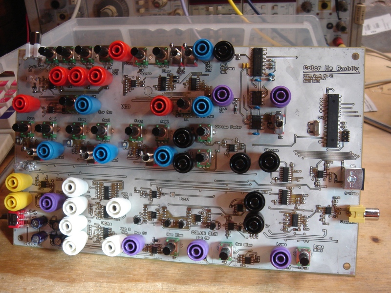
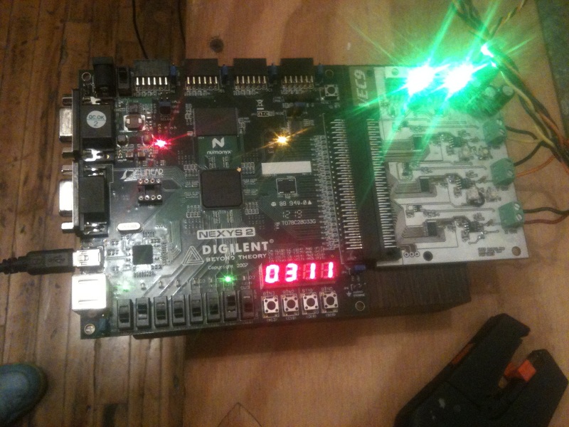
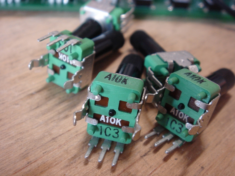
It’s an analog video synthesizer — the sixth prototype I’ve made of one in fact, and this one is finally starting to get OK (you can see some earlier ones if you dig back on the site). It generates NTSC video natively and can spit out either composite or S-Video, most of which looks like so much rainbow flavored wee. But I’m fond of it. The “synthesis” part is basically a processor (an Atmel AVR Atmega, programmed in C and a bit of assembly, at least for now) which generates sync, blanking, and colorburst and a bunch of op amps and transistors which encode control voltages into various video parameters. The majority of the board is taken up by oscillators and signal processors which make or shape incoming waveforms in such a way that they look cool when translated into video.
The synth itself stood up to tons of small children beating on it (some of whom were impressively bright and discovered amazing patches I never would have, and some of whom just wiped peanut butter on the board), I met a bunch of amazing people, and I ended up having a great time despite my initial hey-you-kids-get-that-3d-printer-off-my-lawn attitude. So. THANKS ATMEL and THANKS PAUL you were totally right. And to the grinning hellion with the jelly-hands: I’ve got your number.
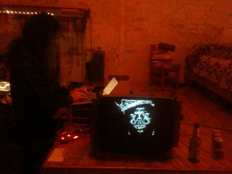
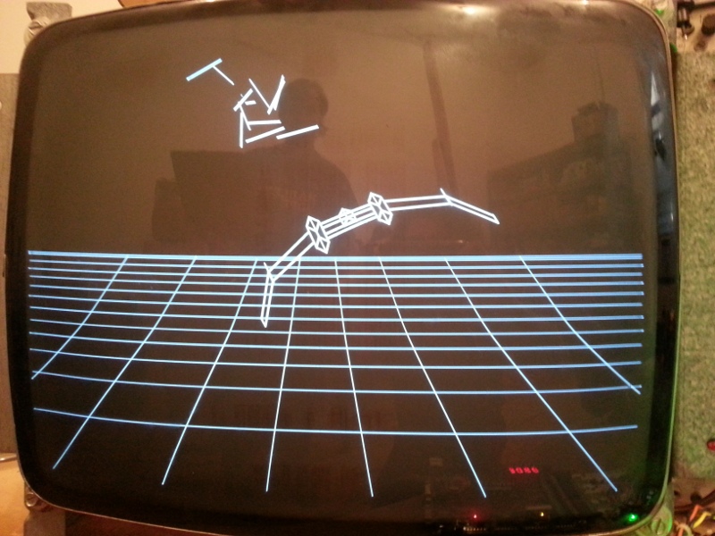
The following photos pretty much describe how it went.
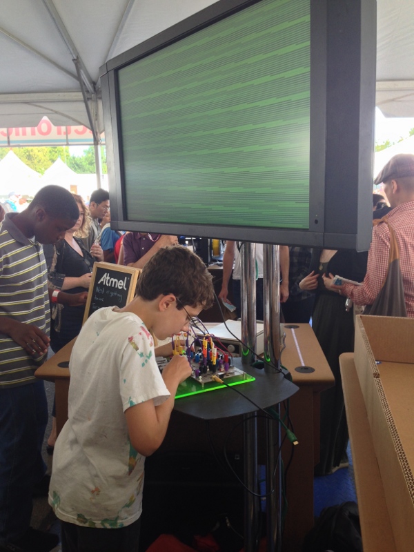
This kid was a genius who made at least two amazing patches that I unceremoniously snatched later. His mom also cracked a joke about chirality.
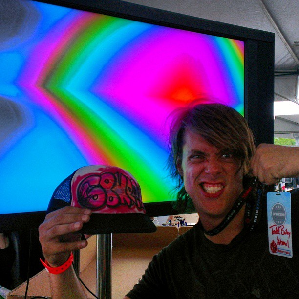
This is the face I make when I steal intellectual property from children. G-UNIT!
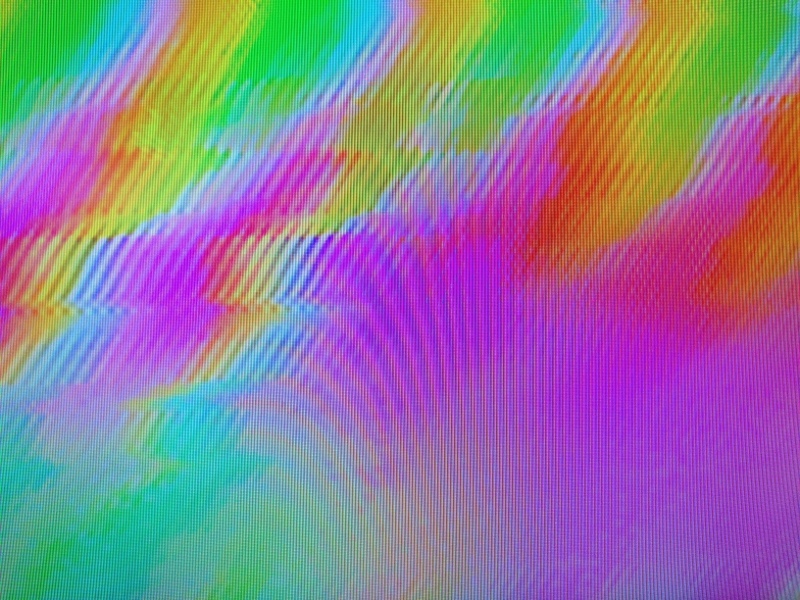
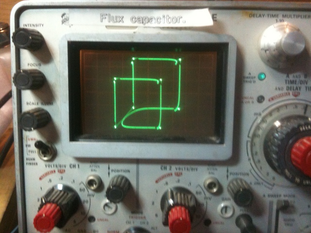
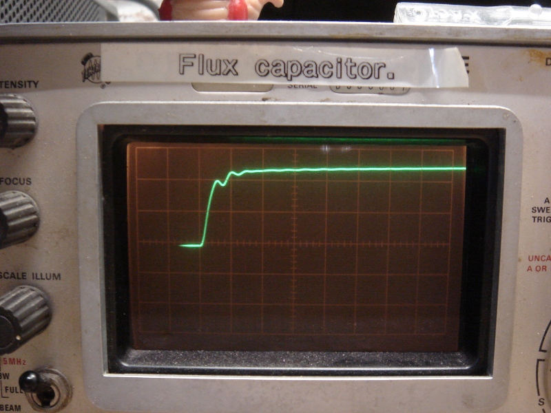
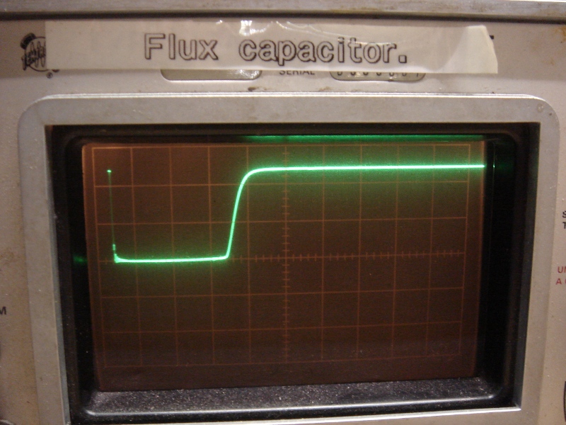
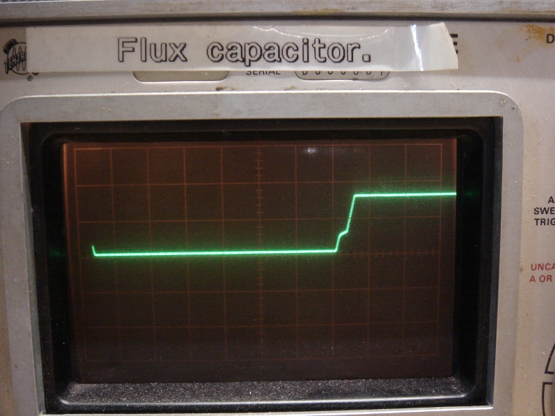
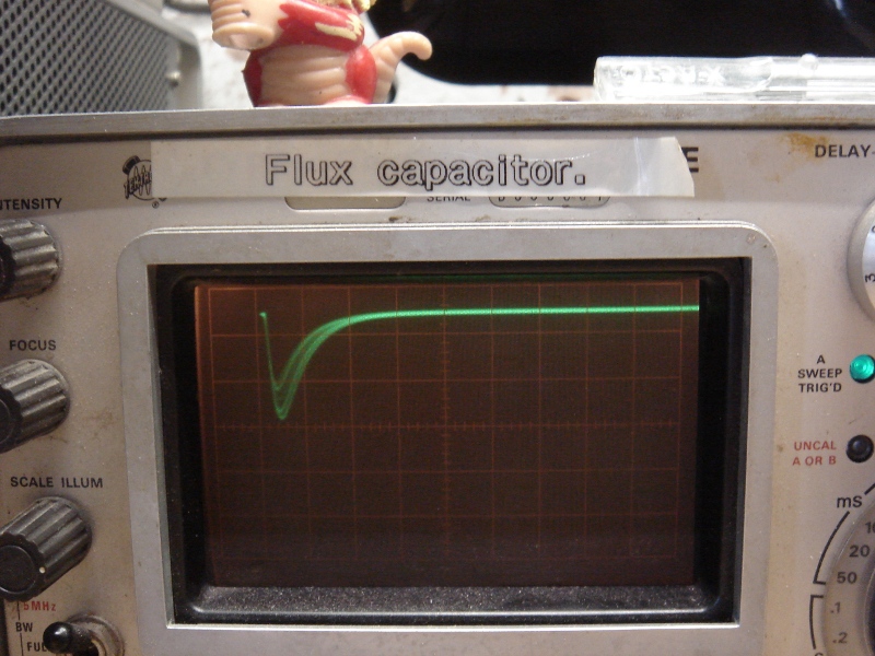
Close up of your standard-issue unicorn vomit.
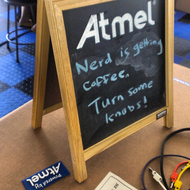
Also, this happened.
Big Ups to Adam and Lexie for taking such great photos and providing stellar moral support.