Posts Tagged ‘Device Characterization’

Adafruit Headphone Amp Design

Saturday, June 5th, 2010

So a few weeks ago I met up with my old buddies Limor and Phil at Adafruit Industries and was griping about work being slow, and they were like, design us a kit.
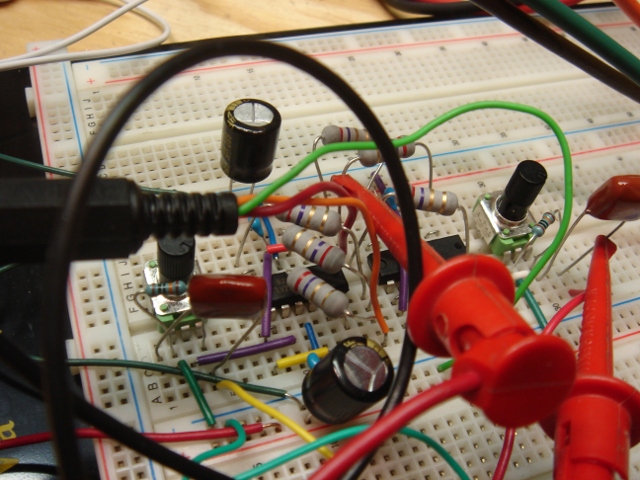
So I did. They wanted a headphone amp which, in their words, “didn’t suck”.
This was really exciting to me! I do a lot of contract work, but I almost NEVER get to do something that’s exclusively analog! Granted, an HPA is not exactly pushing the boundaries of silicon magic in 2010, but I’ll take what I can get. It was a blast. I got to figure out phase margins and characterize ringing and overshoot and make a cable mess (and then worry about the capacitance of it) and just generally get my party on. Plus it was a chance to flex skills in an arena that is full of a lot of crappy designs.

And though the thing is GPL’d,, they did ask me not to go into specifics here or post any schematics or juicy bits UNTIL they have the product out, so until that happens I’m afraid I can’t go into a lot more detail.

Can’t wait to see them lay it out.
Thanks guys!

ALSO — I’d be remiss in not mentioning my friend Shea who had a lot of great advice on this circuit and who has generally forgotten more about audio electronics than I’ll ever know. He re-did the Trident A Range board at Soma Electronic Music Studios when I was back in embedded diapers and let me help re-cap some modules and generally be a solder monkey. I got paid $10 an hour for that and those were still some of the most exciting electronics dollars I ever made.
WTPA2 Initial Hardware Release Announced! With a Pretty Case, too.

Monday, May 31st, 2010

First beta WTPA 2 release date got announced on the Narrat1ve Forum today. I promise to have pictures of a more-or-less-working printed circuit board HERE by July 1st. I’ve already got a rep at Future who I think can save me some dough in parts sourcing, which is good, and I’ve got initial hardware specs (RAM, rotary encoders, new MCU etc) done. The board is starting to come together too. Once all that happens the firmware will start to get changed and I’ll make sure the pretty case fits and looks nice.

WTPA2 Initial Clock Test

Friday, May 21st, 2010

Normally I hate solderless breadboards, but I was kindof inspired by doing recent work with Adafruit that they were OK for iterating through low frequency, proof-of-concepty kind of stuff.

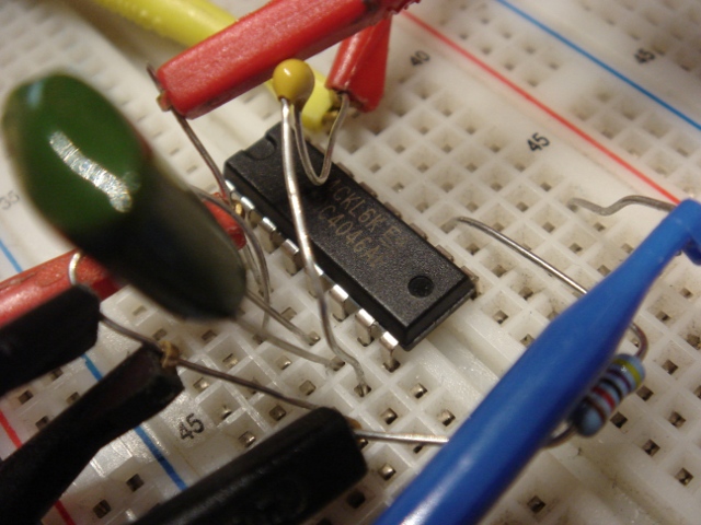
And a good thing I was, too. WTPA2 was slated to have a VCO as a sample clock source, bringing that feature back from the murky WTPA v0.98 days. However, a standard 4046 clock had some troubles, at least as I breadboarded it.

Using a 5v supply, and a CV at the VCO input of 0-5v, and varying the values of the VCO resistors and caps I wasn’t able to get much better than a decade of frequency out of the part. I scribbled these numbers all down on various post-its that no longer make a lot of sense to me, but getting an FMax of 20KHz and an Fmin of <100Hz seemed pretty much impossible, both experimentally and once I bothered to do the math problems in the datasheet. Moreover (and I'd seen this before with the 4046 in video synth stuff) once the CV gets too close to 0v or too close to the positive rail, the oscillator tends to either stop or jump up in frequency. If you haven't already, it's worth referring to the 74HC4046 datasheet while reading this pontification, at the very least to convince yourself that I am not totally making this up.

This is not the most rigorous breakdown, I know, but it was enough to convince me that a standard 2 resistor, 1 cap, and and CV style 4046 VCO was not going to hack it without some kind of magic. I’d been curious about the LM331 V-to-F so I got its datasheet and did some more scratchpad math and convinced myself that it was a lot more likely to come close to what I wanted without serious massage. It’s quite a bit more expensive than the 4046, but at least it’s physically smaller.

Color Me Baddly — New Hit Single “Arbitrary Phase Shift” Out Now.

Thursday, April 22nd, 2010

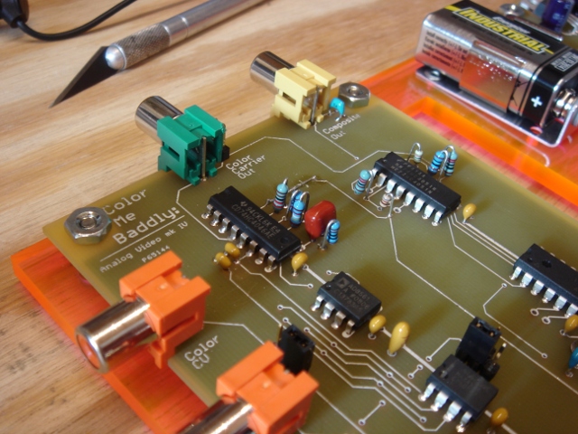
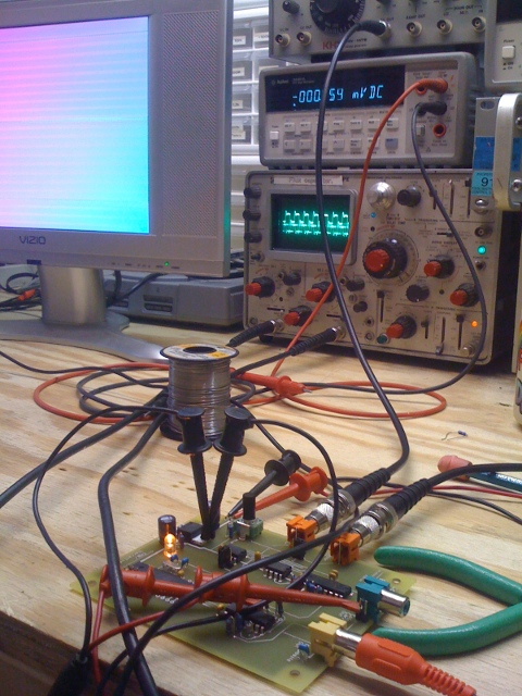
So you can see this PLL video synth guy working his magick here if you look at the scope. That’s a reference colorburst on the top trace, and the bottom trace is that same signal being shifted back and forth around the reference. That’s how NTSC is fixing to get its hue on.

Doing this is the hardest part about generating a color video signal from scratch. “Real” color encoding devices (in NTSC) use something called “IQ Modulation” (really) or QAM (Quadrature Amplitude Modulation) which is what I will shoot for in the next version of this.

I mean, real devices now use processors and ASICs, but.

A close up of the board after he got stuck on some hot pink acrylic.

xo
TB

WTPA2.0 Hardware Feature List Announced!

Monday, April 5th, 2010

It was with great pleasure that I posted the initial list of hardware features that will make it into the next hardware revision of WTPA on the Narrat1ve forum. Until you start seeing boards rolling out, there’s still time to change this stuff, so feel free to let me know what you think and what you’d like to see.

Here they are, as well as what they do for the kit and what they’ll do to the price:
================================================================

1.) WTPA 2 will have 8 controller buttons and not six (the very first one had 5 I think). This will allow us to avoid the dreaded 3-button combo when accessing functions. However, this means two more buttons, and one more shift register IC and socket. This costs more.

2.) There will be a through hole RAM chip. This means the whole kit will be through hole (no smt). This will probably cost about the same, but the board will need to get a little bigger.

3.) The analog sample clock will be based on a 4046 and not an op-amp relaxation oscillator. I can do this because I don’t need the extra op-amp section for overdubbing. This will cost a little less and will also allow CV input to the clock.

4.) The control pot will be replaced with an endless rotary encoder. This will help in all kinds of subtle ways. This may cost a hair more. Given enough pins, I may add a second encoder.

5.) The MCU will be either an Atmega644p or 324p, simply because I want the freedom to add new functions and we’re pretty much out of flash memory on the 164. This will also give us more RAM which may help some of the granularizing functions, and may be able to help with ISR speed if I’m smart about buffering. Those chips are still a 40-pin dip. They cost more.

6.) Some of the values in the analog section will change, which will result in slightly more headroom. This will probably cost about the same.

7.) The bus which is just hanging out doing nothing on the v1 WTPA will be used to access permanent memory. There will be an optional daughterboard which will contain a flash memory chip and will be able to store either 8, 16, or 32 samples depending on how some pricing and availability works out for me. I _might_ implement a sample loader via MIDI. Maybe. The daughterboard will come assembled (all that stuff is small smt biz) and will cost more than $20. Not sure how much more. So permanent storage will be optional.

8.) Instead of a hardware goodie bag, there will be another optional board which will have PCB mounted jacks for MIDI, Audio, and DC. Second to the RAM chip, most build problems in V1 were in the wiring. This should eliminate that problem. This board will mount under the main board. This will _probably_ be more expensive than the goodie bag, but may not be depending on some of the jack pricing.

9.) The routing from the input amp to the AVR will change A LOT. This should lower the noise floor a little.

10.) Because of all these changes, the board will be bigger. Probably not a lot bigger, though. My guess is the price will go up a little too.