WTPA2 Clock Characterization & Pulse Shaping
Wednesday, July 6th, 2011So, after getting back to client work for a minute, I decided to try and nail the clock pulse shaping circuit problem with a more viable solution than throwing in an extra $5 op amp.
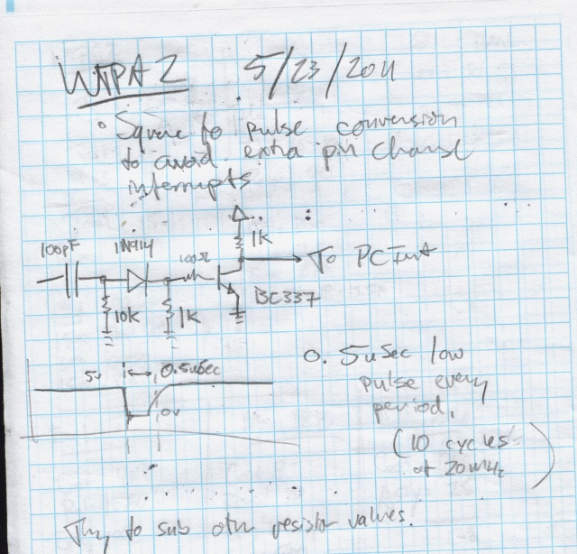
The problem with the original pulse shaper circuit was simply that it was designed with a function generator and not a 20 cent opamp in a RC oscillator. The idea was sound (I think) but the values were not.
The real problem is that the square-to-pulse converter has to shape two different clocks — it’s always driving the same IRQ pin, but it can be hooked up to WTPA2’s 4046 based VCO, or the LM358 based on a user switch. The 4046 is HC logic, and has really square edges. The LM358’s edges are not square, and their slew rate seems frequency dependent also. So, you could optimize components for one or the other, but not both. I did some bench tests to figure out what I needed to change to get this right.
Check it. Here’s the rising edge of the output from the VCO:
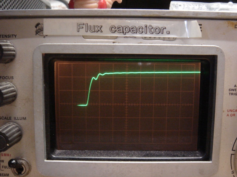
And the corresponding output from the pulse shaping network:
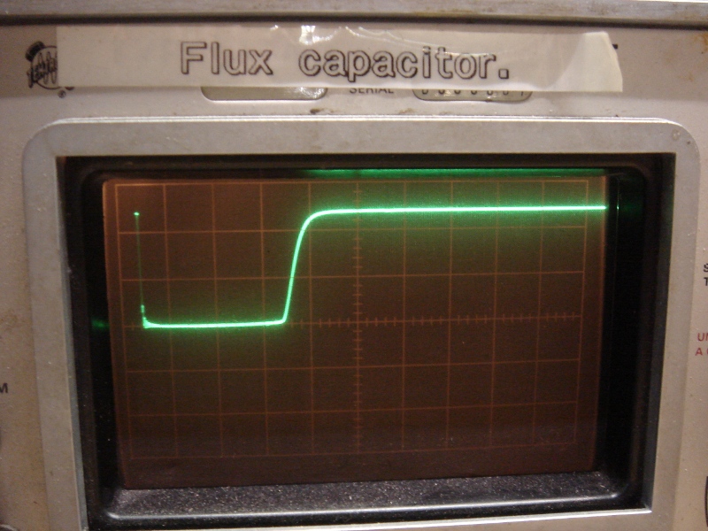
Since we aren’t changing the VCO, this is what we’re gonna call “normal”. The top trace shows a risetime of about 0.1uS (scope is 0.1uS/div, 2v/div) which is quite fast (50V/uS in opamp terms). The ringing here probably has to do with the long ground connection on my probe, and it doesn’t hurt anything except my pride. The bottom trace (the output from the pulse shaper) shows a clean low pulse which is about 6uS long total (2uS/div)
Now, here’s the LM358:
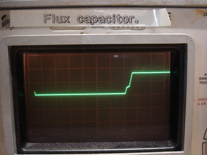
And the corresponding output from the pulse shaping network:
Waaay different! This is the LM358 at its best incidentally — tested at low oscillator frequencies. At higher clock frequencies it slews even more slowly.
The top trace is 10uS/div, and shows a rise time of about 25uS (it’s 60uS with the clock cranked up to 25kHz). Annoyingly, it has that characteristic LM358 style crossover mess. AND it only gets up to about 4v. The rise time is really what matters though, and it is orders of magnitude slower than the 74hc4046. The bottom trace shows the output of the pulse shaper, trying but not quite making it. That dip never makes zero volts and might last 0.25uS. This doesn’t consistently trigger our interrupt-on-change IRQ.
So, the question was what to do. I tested a TLV2462 opamp (my goto op amp for embedded stuff, made by TI, a tank) and it performed equivalently to the 4046, and the pulses worked great. It’s slew rate was rated at 1.6V/uS, which is about 5 times faster than the LM358’s 0.3 V/uS. So it was faster, but not by orders of magnitude. If I could find an opamp which cost about the same as the LM358 and had a better slew rate, that seemed appealing rather than trying to hack up a circuit on 300 already-fabbed boards. The question was how fast we needed to go.
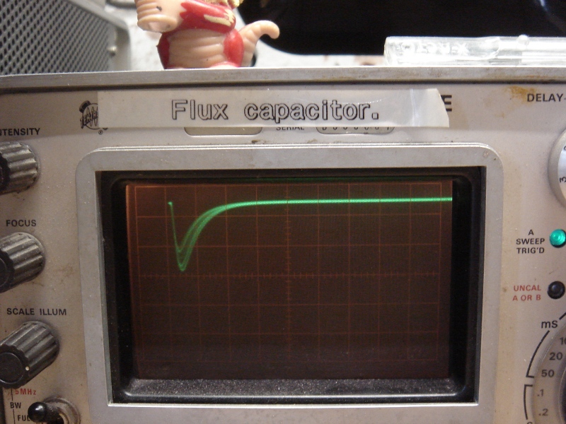
I settled on three opamps for the test: The Microchip MCP6002 (0.6V/us), the Microchip MCP602 (2.3V/uS) and the Texas Instruments TLC272 (5.3V/uS). A few days later I had them all from Digikey. I tested the MCP6002 first, since it was the cheapest. (0.27 at quantity, as opposed to the LM358’s 0.20) Surprise surprise! It worked great on the first try.
Although I didn’t measure the rise time, it looked clean on a scope. The ouptut from the pulse shaper was 6-7uS which is as good as (and more importantly in line with) the logic chip in the VCO. This was also consistent with the TLV2462.
In conclusion, the cheapest and easiest way to solve this problem is (I think) to eat 0.27 per kit and throw in another opamp. Further, the results are interesting because they show that above a certain rise time, performance remains the same. My guess is that there’s a knee point in that filter, and as long as the dominant frequency of the edge is above it, we’re good to go. In this case, a clean 0.6V/uS output was enough to trigger the shaper reliably.
Now that the results are consistent and I’m in tweak mode anyway, I’ll probably try and get those pulse times down by half or so, just in case the ISR gets faster.
Analog is fun, yo.
xoxox
TB