Posts Tagged ‘AVR Programming’

Rainbow Poo, NTSC Synths, and Maker Faire

Monday, September 23rd, 2013

This last weekend, analog man-about-town Paul Rako asked me to show off some nerd stuff I built at the Atmel booth at Maker Faire New York.

To be totally hashtag-real-talk about it: I was skeptical. I have a lot of complicated feelings about Maker Faire, many of which come out when I’ve been drinking, and which I shall save to share with you, dear reader, until we have a beer together. But. I think Paul rules, and I also owe him big time for letting my unwashed self crash the Analog Aficionados parties AND I also use a ton of Atmel parts for both work and fun AND it seemed like the sort of “networkey personal brand-ey” thing that, while it makes me want to slice myself, is usually a good idea in these troubled and humanistic times.

Here’s the thing I showed off:

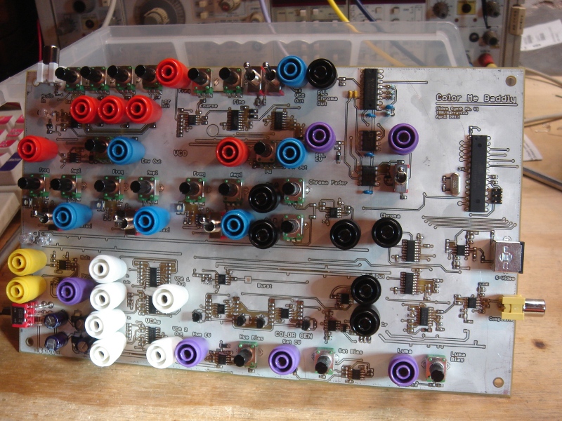
Color Me Baddly Analog Video Synth Mark 6

It’s an analog video synthesizer — the sixth prototype I’ve made of one in fact, and this one is finally starting to get OK (you can see some earlier ones if you dig back on the site). It generates NTSC video natively and can spit out either composite or S-Video, most of which looks like so much rainbow flavored wee. But I’m fond of it. The “synthesis” part is basically a processor (an Atmel AVR Atmega, programmed in C and a bit of assembly, at least for now) which generates sync, blanking, and colorburst and a bunch of op amps and transistors which encode control voltages into various video parameters. The majority of the board is taken up by oscillators and signal processors which make or shape incoming waveforms in such a way that they look cool when translated into video.

The synth itself stood up to tons of small children beating on it (some of whom were impressively bright and discovered amazing patches I never would have, and some of whom just wiped peanut butter on the board), I met a bunch of amazing people, and I ended up having a great time despite my initial hey-you-kids-get-that-3d-printer-off-my-lawn attitude. So. THANKS ATMEL and THANKS PAUL you were totally right. And to the grinning hellion with the jelly-hands: I’ve got your number.

The following photos pretty much describe how it went.
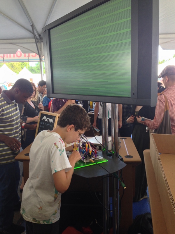
MF_Kid
This kid was a genius who made at least two amazing patches that I unceremoniously snatched later. His mom also cracked a joke about chirality.

68Krewgetyrdixout
This is the face I make when I steal intellectual property from children. G-UNIT!

MF_Rainbow_01
Close up of your standard-issue unicorn vomit.

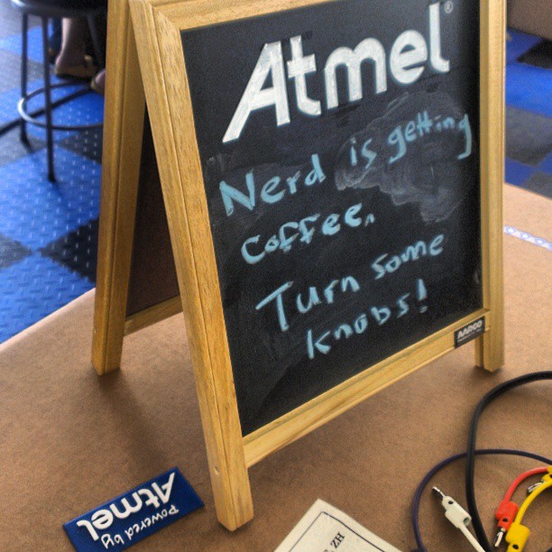
MF_Coffee
Also, this happened.

Big Ups to Adam and Lexie for taking such great photos and providing stellar moral support.
WTPA2 Proto Starting to Pwn

Monday, September 20th, 2010

So the first iteration of WTPA2 has some dumbass mistakes — bus problems during flashing hardware (missing pullups), some switch latch goofiness, and turns out all those RC filters in the encoder datasheet really ARE a good idea. However, once all the traces got cut and the little merce-resistors got in place, the thing works great. The VCO is spot on. More importantly, so is the FLASH MEMORY! The SST flash kinda sucks in that it’s not fancy and requires you to manage erasing-before-writing and demands paying attention to buffering and stuff, but you can totally turn off WTPA2 and turn it back on and keep playing with that perfect burp sound you made.

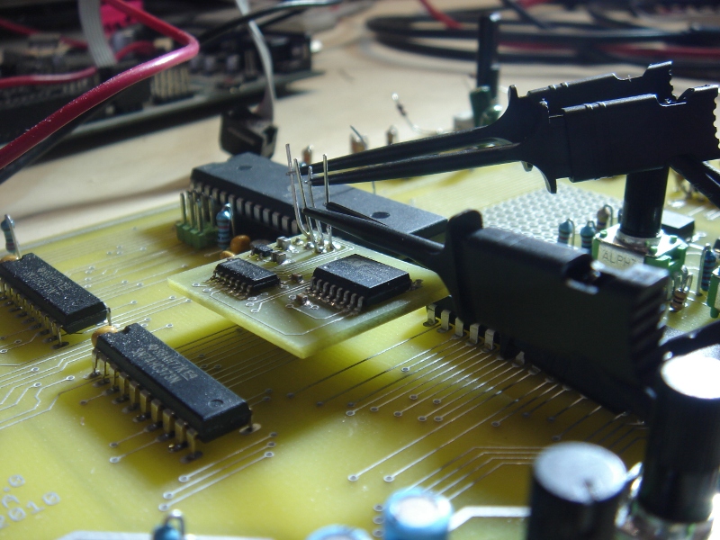
Logic analyzer bus-sniffing.

Also, equally excitingly, the ISR has gotten A LOT FASTER — this proto recorded and played back just fine at 45kHz. A lot of this had to do with taking some very good suggestions from Olivier over at Mutable Instruments (of the Shruthi-1 fame) who is a great programmer and shamed me out of much laziness in my code.
As if that wasn’t enough, I finally licked the lion’s share of the noise sources that plagued WTPA1. I’d always been really careful about analog signal routing, but I’d been pretty cavalier about ignoring the hell out of some of the “Analog Noise Cancelling Techniques” in the Atmega datasheet. Turns out I traced most of the noise back to on-chip activity which had to do with reading and writing to the SRAM (toggling GPIOs) while the ADC conversion was taking place. I moved some of the accesses around and that NAILED it. Like, totally duh!

Also, re: the picture — I bought one of those Saleae Logic analyzers the moment they started supporting Linux because it seemed like a cool toy. But it’s actually really useful and works great! In addition to actually seeing what’s going on over the bus (as attached here) it’s REALLY handy for timing ISRs. Like, you toggle a pin high when you vector, and then low again when you exit. I always did this with a scope, but the logic analyzer is great because it records a lot of them and you can analyze variation, see what happens between several different calls, use many channels, etc etc.

Anyhoo, WTPA2 had an exciting week. It may take a break for a minute as I have a really busy winter coming up, but still, good time.
xo
TB

Color Me Baddly Gerbers — a companion video tool.

Tuesday, April 20th, 2010

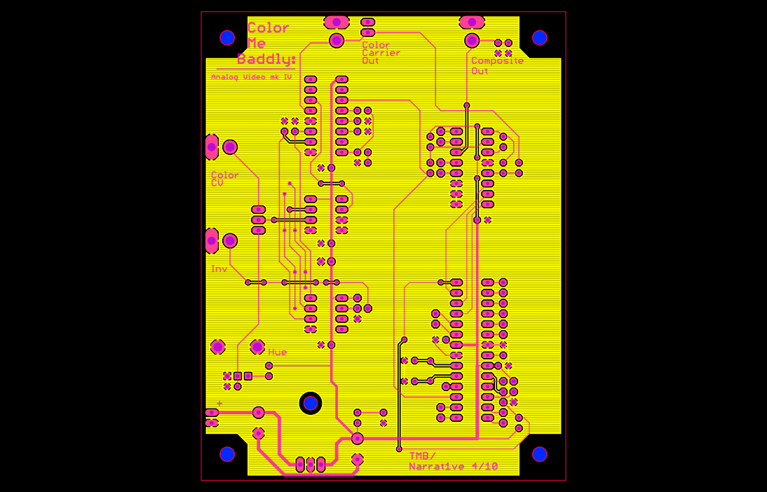
Just for grins, while I was waiting for the PCBs to come in, I decided to lay out a new design for color synthesis that I’d been fooling around with. This, again, is the gerber file.

The sync and blanking circuits in the above are fairly pedestrian — they’re just an AVR running at 14.318 MHz, which controls a 4051 to gate in the correct resistor values to get sync and blanking levels into 75 ohms. This part is pretty much exactly the same as the circuit from Owen Osborn’s old CA synth (which is a really elegant piece of engineering, I think). The AVR generates the colorburst and color carrier also using a hardware timer to divide the crystal frequency by 4. This means this prototype ain’t gonna do PAL. Sorry.

To my mind, the really interesting thing is the way in which color gets generated. Hue is encoded in analog composite video by _PHASE SHIFT_ of a carrier wave. Someone very smart and very good at electronics figured that out a long time ago. I’ve built synths in past which use the AD724 (lame) and varactor diodes to give continuously variable integration.

The varactors are actually a pretty badass way of doing it — they’re fast and kinda nonlinear and totally work, but it requires A LOT of stages of this to get 360 degrees of shift (enough for all the colors a TV can display). Also, (in addition to not being super cheap) the really good varactors are small SMT devices. I personally don’t care, but some of the cave-people with soldering irons who frequent this site occasionally express concern about this sort of thing and their poor tired eyeballs etc etc. Generally when this happens I turn up the Brandenburg Concertos and have my manservant pour me another Campari spritzer, but this time I decided the unwashed masses should have some cake too.

So.

It took a lot of searching and fiddling to find something that I thought would work, that was both elegant and cheap and didn’t require exotic components or a sensitive board layout or weird supply rails or whatever. I had this suspicion that a PLL could do what I wanted, cause you know, its job is to party with phase. PLLs regularly work at or above colorburst frequencies (3.58MHz) which is also good because it means they aren’t on the edge of some spec.

The other idea I had (a voltage controlled all-pass filter) was generally too hard to do at frequency ranges that high (the LM13700 won’t slew anywhere near that fast, for instance). Other than designing an OTA which works at those frequencies (on my list of things to do, along with dating supermodels, designing invincible armor and generally running Stark Enterprises) I wasn’t sure how to implement this in a simple way.

PLLs are not the easiest circuits to understand (for me, anyway). But they are cheap and ubiquitous and many very smart people have written a lot about them. Eventually I stumbled across this circuit in EDN. The description with it is brief, but pithy, and explains the essential details of what I wanted to do.

Armed with this I was able to create a new design, standing on the shoulders of great nerds past. And when UPS shows up, I’ll know how well it (as well as the Mess Tool) works out!

Xoxo, TB

WTPA Firmware Rev 3 Released!

Thursday, April 1st, 2010

OK. I finished shoe-horning necessary functions into this beast. Somebody tell me something that needs to change or this beta becomes legit by tomorrow.
There are a whopping 12 bytes left in memory, and the OS has had a lot of fat trimmed.

Here’s beta 4 (final):
http://www.narrat1ve.com/WTPA_Firmware_0x03.tar.gz

And here’s the R3 changelog, so if you don’t know, now you know:

Firmware Version 0x03:
==============================================================================
Wed Sep 2 09:37:49 CDT 2009

Done:
— Hardcoded explicit bank start address variables into define statements. They are constants in our current system; this will prevent them from being overwritten, save us some RAM and some cycles.
— Sample Start / Window / Endpoint editing, realtime adjustment. Samples with will reverse when the start point is put after the endpoint.
— Separated the “bail” command for FX and loop adjustments in MIDI
— Re-number MIDI CCs
— Added MIDI option to edit samples with wide range or tighter resolution (editing pot is an 8-bit value, MIDI is 7)
— Added “edit mode” which sucks. But allows you to stop holding down three buttons while you edit a sample.
— Removed some un- or underused softclock (timer) and Uart functions — we’re running low on flash memory.
— Divided AudioHandler routines into bank-specific routines for ISR speed BUT
–> this means we are way over memory. So, got rid of intro sequence, debug mode, all sawtooth stuff, removed some timer functions, changed MIDI handling (don’t recognize bytes we don’t use anyway), changed LED blink functions (all blink times the same)
–> Also kilt the random number init code. Changed pinning in multiply-output mode.

xo
TB

Playstation PGA Golf Tweakery

Thursday, March 18th, 2010

More new media art binnis for Cory.
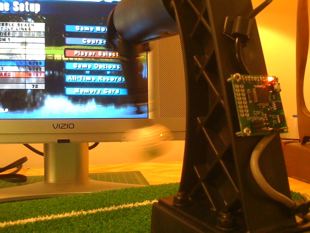
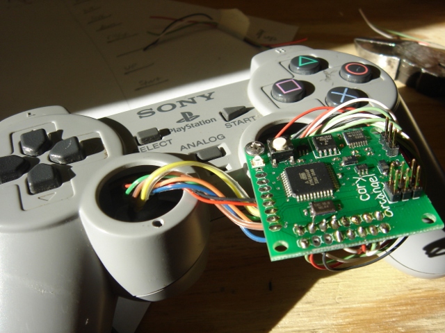
This is basically an installation specific version of that little SBC/datalogger thingy I made. This one hangs out on a silly putting practice stand and plays back controller keypresses on a PS1 when you whack the ball.

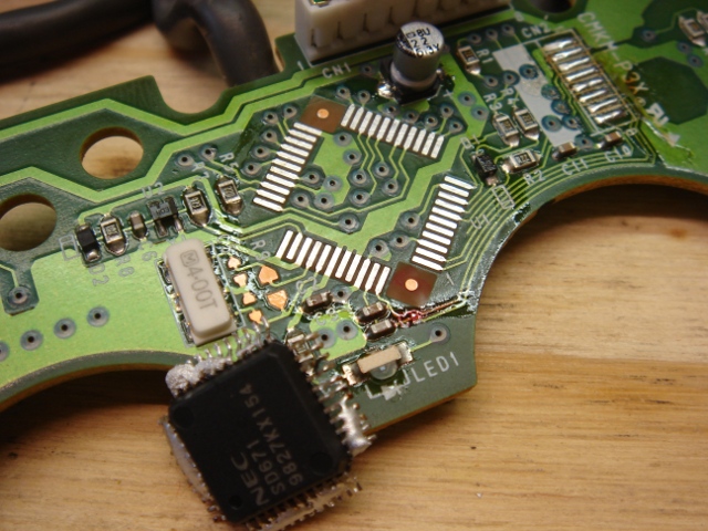
To do this, first (well, first you design a weird SBC for new media artists, but) you replace the controller’s MCU (in this case some proprietary TQFP guy) and figure out where his data lines are. I happened to already know that the PS1 basically talks SPI. Some low temp solder and a rework station was used to perform said brain surgery.

The datalines and switch lines are then brought out to my baby, where it handles communication with the PS1. You can then record the game into it, put it on your PC, and do whatever mess you need to with the data.

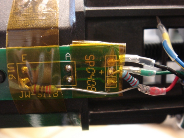
That golf tee had a set of optical photointerrupters inside it which were originally used to keep track of how hard you hit the ball and how badly you shanked it. I wired one of them to just give me a clean square wave when the ball moved appreciably, since that’s all we needed to know for our game. The code on the “TiVo” had to get changed to account for this, which was no biggie.

Eventually, these things had to get re-built cause Cory got worried that art students would have a few too many PBRs at the openings and eventually whiff and take out one of the external PCBs. I ended up ultimately shock mounting them inside the stand itself. That’s also why Cory is a good client, because he is almost certainly correct. There is a good chance that would have happened before leaving Narrat1ve labs :-)