Posts Tagged ‘Hardware’

Coffee Engineering

Thursday, April 1st, 2010

So my housemate has this really fancypants french press which is all like “she think she cute” but actually ends up making the siltiest coffee ever. You’d think that with all the video business going on I would let it slide but I ended up ordering a bunch of stainless steel cloth and some silicone washers from McMaster and going to town on that piece.

I made an additional filter with a piece of 200 x 200 mesh which according to McMaster is more than good enough to keep flour-sized particles out, and stood it off on said washer (compressed to keep particles from coming up around the shaft). The french press got a better but damned if there still wasn’t silt. I decided to worry about my job again.

Playstation PGA Golf Tweakery

Thursday, March 18th, 2010

More new media art binnis for Cory.
This is basically an installation specific version of that little SBC/datalogger thingy I made. This one hangs out on a silly putting practice stand and plays back controller keypresses on a PS1 when you whack the ball.

To do this, first (well, first you design a weird SBC for new media artists, but) you replace the controller’s MCU (in this case some proprietary TQFP guy) and figure out where his data lines are. I happened to already know that the PS1 basically talks SPI. Some low temp solder and a rework station was used to perform said brain surgery.

The datalines and switch lines are then brought out to my baby, where it handles communication with the PS1. You can then record the game into it, put it on your PC, and do whatever mess you need to with the data.

That golf tee had a set of optical photointerrupters inside it which were originally used to keep track of how hard you hit the ball and how badly you shanked it. I wired one of them to just give me a clean square wave when the ball moved appreciably, since that’s all we needed to know for our game. The code on the “TiVo” had to get changed to account for this, which was no biggie.

Eventually, these things had to get re-built cause Cory got worried that art students would have a few too many PBRs at the openings and eventually whiff and take out one of the external PCBs. I ended up ultimately shock mounting them inside the stand itself. That’s also why Cory is a good client, because he is almost certainly correct. There is a good chance that would have happened before leaving Narrat1ve labs :-)

Ph’nglui mglw’nafh Remoc R’lyeh wgah’nagl fhtagn, or, Everybody Loves Remoc

Sunday, January 17th, 2010

At the end of January I drove back to the city of heavenly taquerias and got jiggy with installing new brains in Remoc, just the cutesy wootsiest Elder God you could ever hope to meet!

Our boy assumed this position for many hours. Quoth the security ladies at the front desk, “Your Monster is all Drunked over!”

Here’s what the sensors look like in vivo. The little wire goes to a sheet of copper tape which is adhered to the inside of one of Remoc’s surfaces where he’ll be sensing touch (for instance, his finger — you’ll never guess what happens if you pull it). These plates are all of different sizes and shapes, and of accordingly make for different signal strengths on the output. They are also pretty close to one another sometimes and it certainly seems from looking at the ADC readings like there are some irritiating interactions between some sensors. If I did this again, they would each have an enable line and be polled sequentially. But.

The little boards get stuck down somewhere convenient and close to the tape, and then the more-or-less DC sensor signal is shuttled back through a cable.

Finally, the guy who sculpted Remoc managed to set his entire body cavity on fire shortly after all the copper tape and wiring was installed. This adds a real “wild card” element to the sensor system which keeps it fun!

Anyhoo, after a long install, he was back up and gibbering, and there was much rejoicing!


[Ed note: since this time, word has again arisen from the West that the cultists are stirring. It is likely this is not the last time we will sojourn to the Comer, dear reader, or as I like to call it, “Baby Boo Miskatonic”]

The Joy Demon Cont’d

Sunday, January 10th, 2010

So sometime at the beginning of 2010 the sick children of Chicago set up a fuss looking for their monster again. You could hear them all the way from Brooklyn. Again, my guilt was heavy. Again, I made some stuff.


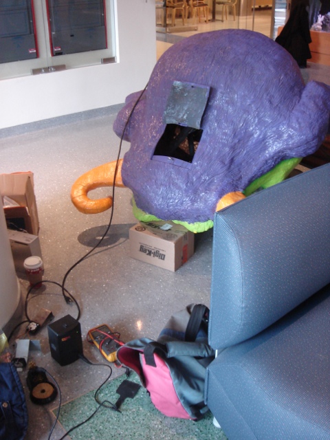
An introduction of what Remoc does is in order I guess. He’s basically a bigass toy that senses when little kids touch him in different spots and plays various games with them. He laughs, he cries. He may or may not be better than Cats. He also goes to sleep at night, sings songs, and has a weird interactive thermometer. He farts a lot. When he behaves, he’s kind of fun.

His memory and play pattern live on an SBC designed by my buddy Todd Squires which we used at the old toy company and affectionately call the toybrain (version 4). The TB4 was fine.

There was no real way to salvage most of the rest of Remoc’s old brain. There was a crappy class AB audio amp I put in which got way too hot, his touchsensor circuits were noise prone and also temperature sensitive, and his LED supply tended to go out of regulation when too many lights in the thermometer stayed on, and he got confused easily about time-of-day stuff if you turned his supply off. His eyeballs were light bulbs which burnt out (that was a committee decision, but). None of this was good.

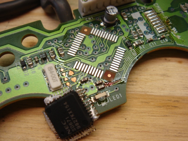
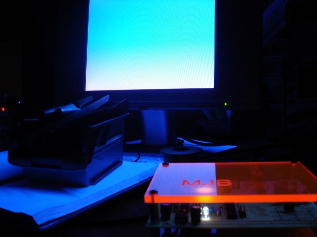
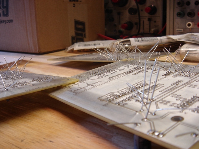
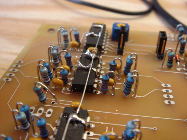
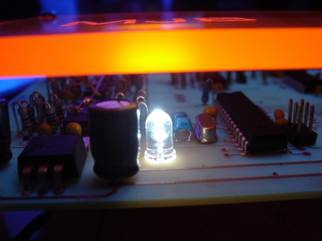
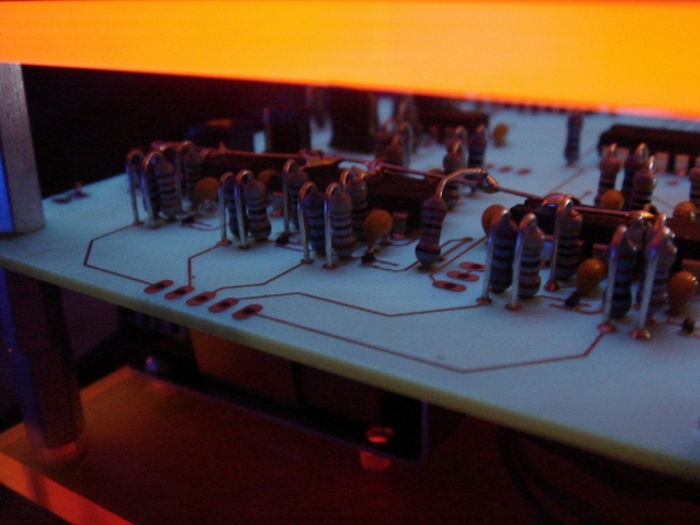
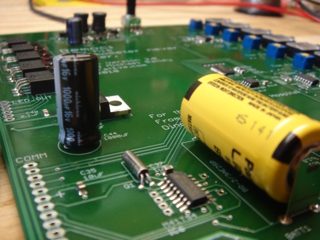
His new brain boards (above) dealt with all this stuff. 2010 saw Remoc get new MOSFETs to run all his lights, a new audio amp, and a proper RTC with a ginormous battery for backup. More importantly, he got a bunch of precision opamps and a multichannel ADC to handle input from the touchsensors.

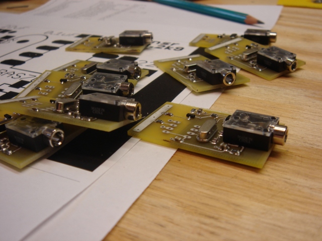
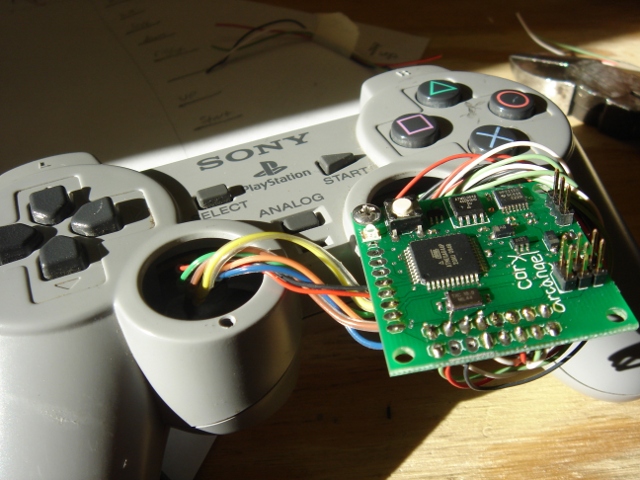
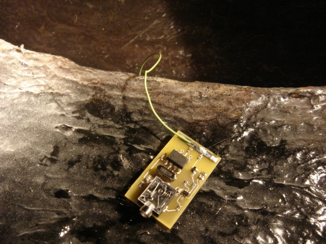
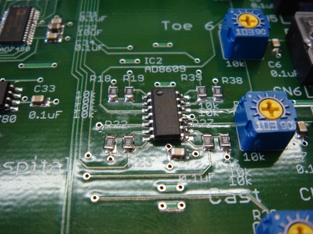
The touchsensors were actually fun to make. They’re an AVR which generates a crystal derived square wave (laziness on my part, and tunability. The generator could have been a logic gate or any crystal clock circuit really, although the programmable chip provided fudge room which I didn’t [and hopefully won’t] need) and drives it through a resistor to whatever gnarly sensor plate you have, and then filters and rectifies what’s left. They use hand capacitance to form a variable RC filter; the output of this device is a voltage which is inversely proportional to the capacitance at the sensing node. Not perfect, but pretty good. These sensors also use 1/8″ cables to carry power, ground, and signal, cause 1/8″ cables are cheap and promised to make wiring the beast a lot easier.

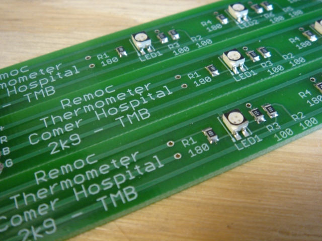
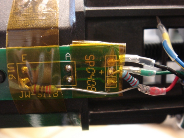
The thermometer. Some SMT LEDs on a stick. Yaaaawn.

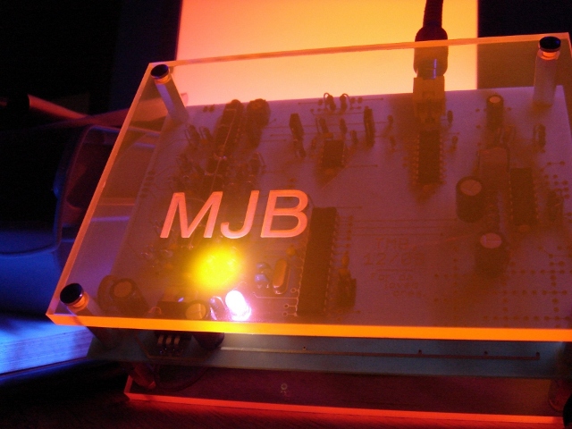
All this stuff got packed up to schelp to Chicago.

I Know What Moms Like

Sunday, December 20th, 2009

Though she probably would have been more interested in a Steven King book and some Calphalon pots, I decided to build a video synthesizer for my Mom for Christmas. I also built one for my girl, who is generally more into blacklights than mom and one for me, because, you know, ho ho ho.


There were lots of reasons to do this. Partially because I think it’s cool to give gifts you make and less altruistically because I was still geeked about the little varactor synth that I’d made and wanted to do a new revision of it.

This synth still generates all the housekeeping signals with an AVR (as well as the colorburst) and switches them around with a 4051 multiplexer. However, it adds a clamp circuit which allowed control of color saturation (the old version was fully saturated color all the time) and a DC offset circuit which controlled brightness (that knob was also at 11). Those circuits worked _OK_ but not great, and I found I generally liked the results when everything was full out. There’s also an option to invert the color carrier, which WAS cool, in an epileptic kind of way. The sync signals on this guy were not _quite_ at the right levels either.


The idea is basically the same as the last varactor synth; except there are now multiple stages of RC phase shift. Each stage uses a SMV1255 “Hyperabrupt Junction Tuning Varactor” as the cap in that RC which is driven by a control voltage. Each stage is also buffered by an XOR gate, to square the signal back up after passing through the RC. One thing I also screwed up in this design was running the chain of buffers NON-INVERTING. This meant that with big phase shifts (which also meant big attenuation from the filter) the color carrier would eventually disappear, I assume because of the asymmetrical thresholds in the gates. On a scope you’d just see the duty cycle getting farther and farther from 50% and then just disappear entirely. The big solder mess here shows the workaround I did to fix this, which helped. Using comparators would help even more. Using a different circuit topology entirely would prove to be the most helpful….

Still this synth was pretty cool. Because it was for Moms and GFs, it was designed to be standalone and not require any inputs. There’s a little prototyping area where I made some function generators to make repetitive waveforms to drive the various color stuff.

xo
TB