Posts Tagged ‘Electronics Advice’

I Know What Moms Like

Sunday, December 20th, 2009

Though she probably would have been more interested in a Steven King book and some Calphalon pots, I decided to build a video synthesizer for my Mom for Christmas. I also built one for my girl, who is generally more into blacklights than mom and one for me, because, you know, ho ho ho.


There were lots of reasons to do this. Partially because I think it’s cool to give gifts you make and less altruistically because I was still geeked about the little varactor synth that I’d made and wanted to do a new revision of it.

This synth still generates all the housekeeping signals with an AVR (as well as the colorburst) and switches them around with a 4051 multiplexer. However, it adds a clamp circuit which allowed control of color saturation (the old version was fully saturated color all the time) and a DC offset circuit which controlled brightness (that knob was also at 11). Those circuits worked _OK_ but not great, and I found I generally liked the results when everything was full out. There’s also an option to invert the color carrier, which WAS cool, in an epileptic kind of way. The sync signals on this guy were not _quite_ at the right levels either.


The idea is basically the same as the last varactor synth; except there are now multiple stages of RC phase shift. Each stage uses a SMV1255 “Hyperabrupt Junction Tuning Varactor” as the cap in that RC which is driven by a control voltage. Each stage is also buffered by an XOR gate, to square the signal back up after passing through the RC. One thing I also screwed up in this design was running the chain of buffers NON-INVERTING. This meant that with big phase shifts (which also meant big attenuation from the filter) the color carrier would eventually disappear, I assume because of the asymmetrical thresholds in the gates. On a scope you’d just see the duty cycle getting farther and farther from 50% and then just disappear entirely. The big solder mess here shows the workaround I did to fix this, which helped. Using comparators would help even more. Using a different circuit topology entirely would prove to be the most helpful….

Still this synth was pretty cool. Because it was for Moms and GFs, it was designed to be standalone and not require any inputs. There’s a little prototyping area where I made some function generators to make repetitive waveforms to drive the various color stuff.

xo
TB

WTPA v1.0 Kit Boards Ordered

Monday, March 23rd, 2009

Free Technical Advice: When the Fluke suggests you change its battery, change its battery.

Better: I ordered the REAL BOARDS from China today! I’ll spare you some more pretty gerber files, even though the latest ones are by far the most lovely. Summarily filed under the “breaking some eggs” part of the process. That having been said, my people at PCBCart have so far surprised and pleased me with being fast and friendly. I am now Significantly Monetarily Committed to Not Screwing This Up. I also ordered another set of bare test boards from Advanced Circuits to continue to mess with while I wait for the Mona Lisas to show up.
In other news, my tube amp is on the fritz again. Why I thought tube gear was romantic and cool at some point in my life is beyond me. I swear I’m this close to replacing the chassis bolts with thumbscrews, or better yet replacing the 6L6s with MOSFETs.

Finally, for those of you who haven’t noticed already, there’s a little link above which gives the details about WTPA in a nutshell as the uninitiated had a really hard time figuring out what all this gibberish was about.

WTPA v0.98 Review and Shakedown!

Wednesday, March 18th, 2009


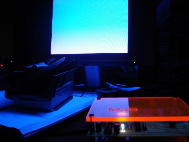
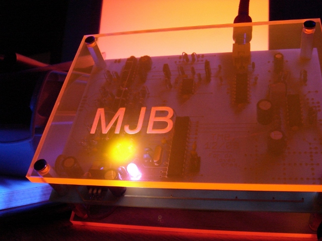
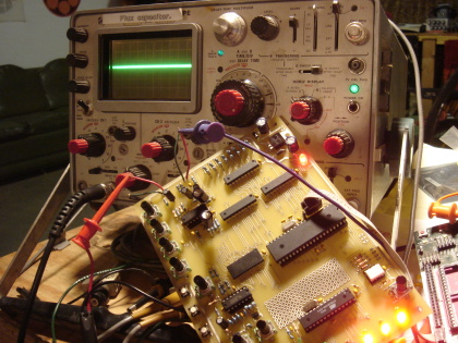
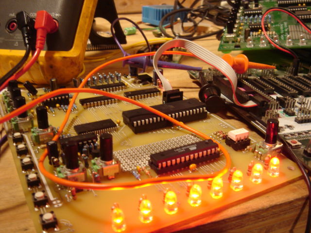
So I got the test PCBs Monday, bare as the day they were born. The last couple days I’ve been going through all the circuits and checking the hardware for problems, bugs, things to optimize, and stuff that would otherwise be Bad To Deal With in a run of 200 units.
The good news: The third rev of boards does more or less all the stuff it is supposed to, and has most of the performance improvements I’d expected. However, nothing is perfect.

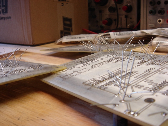
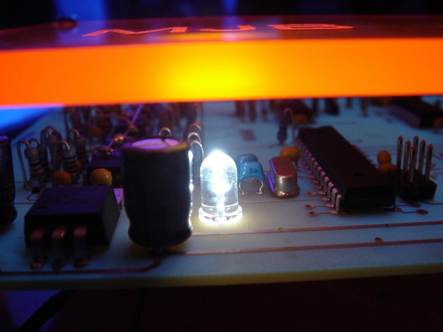
First, let me give you young nerds a piece of advice. Become rich. Then use your dough to buy prototype boards that have a soldermask. Good lord. You will save yourself hours in debugging stupid soldering problems, and gray hair in debugging other problems which you may at first erroneously attribute to solder bridges.
Bare PCBs do offer an advantage in that they’re easy to probe wherever you need to, and all that exposed tin makes it easy to solder fixes in, but in general they will make you crazy at least once with some weird connection that you didn’t mean to make. That was the first round of problems I had to solve.

With those out of the way came the first real, serious, problem: The VCO. The VCO got incorporated in the last board rev and I dutifully wanked on it a few times and then set it aside to deal with other problems. This in retrospect was quite stupid, because if I had paid more attention I could’ve saved myself a lot of time and a little false advertising.
It turns out that the VCO design I used (ripped wholesale, with a few changes, from Horowitz and Hill p. 240, who I’m pretty sure in turn ripped it wholesale-with-changes from the LM324 datasheet) is good in many regards. It is single supply and simple. It requires only opamps and a fairly generic transistor or FET. The problem came in trying to tune the monster over a wide range. Though the TLV2474 opamps I’m using are pretty good at RRIO, they aren’t perfect.
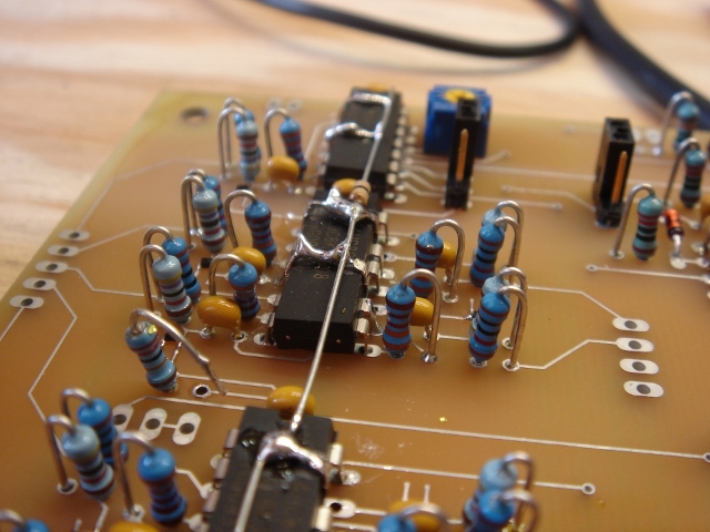
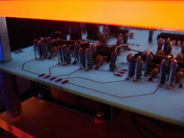
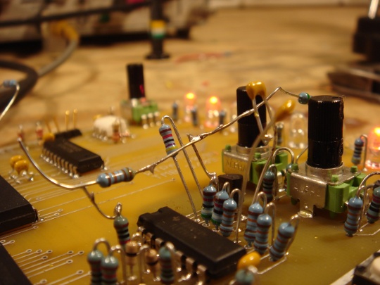
All the drama occurred when the CV was some small number of millivolts from the bottom rail. The ‘2474s don’t really want to drive that low, so I made the little Merce Cunningham looking mess of dancing resistors (pictured above) to help pull them there. Simple enough, but a little ugly.
Approaching REALLY closer to the rail (say within 10mV or less) the VCO stops responding in anything approaching a linear fashion and gets jittery and tends to drop out. Normally I wouldn’t care and would just bias the CVs above 10mV, but that ends up being a significant amount of tuning in the low-sample rate range. Which is silly. _NO_ op amp is that good, really, and no good design should try and expect one to be assuming it isn’t colliding particles or something.
With a marathon all-nighter / all-dayer the best performance I could get from the VCO was a not-so-great 2kHz to 16kHz, a tuning range of 8-to-1. This sucks. In retrospect the humble relaxation oscillator of the first WTPA did something like 60-to-1.

I fiddled around trying to get another VCO design breadboarded for a little while, but all the good ones I know use an OTA. I’ve seen some designs with analog switches and of course plenty with specialized VCO ICs, but I had three op amp sections and a dream. The final decision was to drop the VCO, return to the traditional relaxation oscillator, and reduce the opamp from a quad to a dual. Even Saving You Money(tm) in the process.

For those of you crying “Noooo! How will I make it talk to my Modular?” first let me say — samplers usually don’t talk to modular synthesizers, you’re spoilt. Second, let me say, because I love you, and because that’s a weird and cool idea, I’ve worked out a way to make the sampler’s oscillator clock sync up to audio inputs — so you’re losing a VCO, but you’re gaining a sync! This means that now you can synchronize your samples to your vocal line, synth line, guitar, or any signal in the audio frequency range.
This should work pretty reliably — I’ll know soon. I can no longer say “The only sampler with a VCO” but I think the new effect will probably be cooler anyway.

Everything else: I found a hardware bug in the in-circuit serial programming section related to changing around the data bus. I fixed with some pullup resistors. After that I made sure the switches and LEDs worked with the new bus structure. It’s technically still possible to PWM the LEDs and maybe I’ll do that sometime before release, but it’s low on the list. Next I quantified the bus-turnaround time related to the bus routing changes, and they’re almost invisible. It took some NOPs in the ISR, but I bet I can optimize those out later. I tested the MIDI output — so far WTPA has only received midi messages. But today it took charge, such as it can.
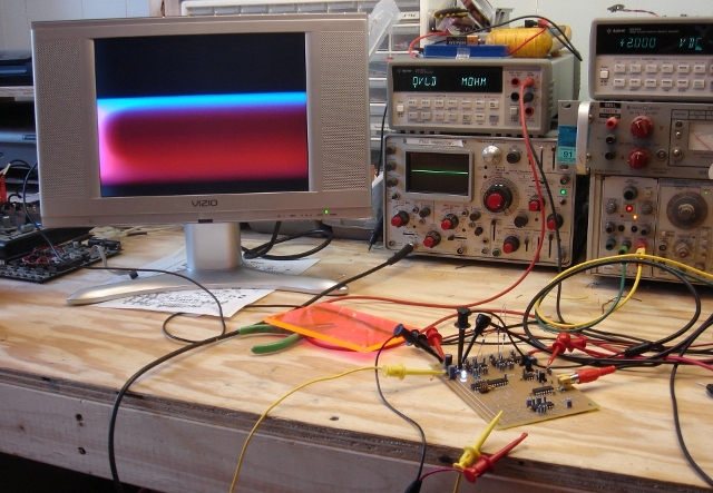
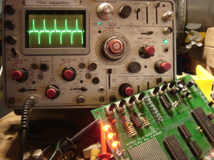
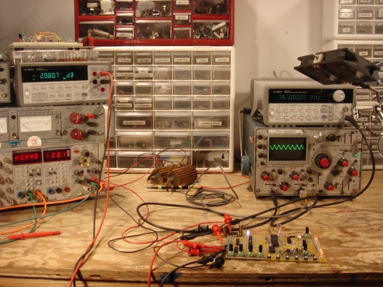
Finally, I took a look at the audio path. This was important and enlightening. Using a function generator and a fancypants benchtop meter set to take dB readings, I figured out the f3dB points for all the different audio paths through the system. They were pretty good — the first reading showed the audio range of the sampler’s pass-through and DAC paths to be about 14Hz-356kHz (pictured above). Not bad!
Still, as a rule of thumb (also ganked from H&H) I try and position f3dB points 10 times greater or less than the frequency of interest to avoid phase shifts in the audio range. You know what they say about phase shifts, right? “They make for weak ass west coast bass, not that Miami shit.” That’s what I heard them say.
Anyway, I got the range for those paths to be more like 2.8Hz to 370kHz with a few changes. In the overdub path I managed to actually DC couple some of the connections which means that there should be no loss in that path relative to the rest of the sampler.
Giving it the listen test, it sounds Really Good. I’m happy with the audio quality. It’s nice and quiet where it should be, with good frequency response, leaving it free to Expose Da Crust in all the important parts.

Finally, there was one more valid thing I found. In an effort to keep impedances (and costs) low I settled on two values of potentiometer for the final thing — a 500k audio taper for the input and output amp gain controls and 1k linear pots for everything else. In all the audio controls on the board, the 1k pots have a resistor from the wiper to ground to approximate a logarithmic curve (and make your life silky smooth). This means that the total resistance in some places in circuit ends up being pretty darn low. Although this does keep noise pickup low and the top f3dB point high, it also ends up working out the driving opamps something fierce. My hot rail-to-rail output doesn’t swing nearly as rail-to-rail as it used to. This of course means less usable bits in our sample. I can fix this a little by chaning the tapering resistors on the pots, but the right thing to do would be to bump the pots up to 10k and scale their related circuits. Easy enough, if I didn’t have a boatload of pots on the way from China already. The ENOB isn’t terrible, but it could be a little better. Hey, what’s a design if there isn’t room for revision?

Lastly, before I leave the soapbox, I’d like to take this opportunity to show this off as yet another example of an old TMB truism: Analog Be Harder Than Digital. Not better, but harder, and perhaps by association more noble and romantic.
While I was frantically breadboarding crappy VCOs, I came across this app note in which that continuous font of inspiration, Jim Williams, designs like 10 analog circuits which are complicated enough that they make my head spin even after reading his explanations, and he figures them out for shits in his garage or something, while on vacation. There’s a badass VCO in there which tests my understanding, and whose makeup is also (or consequently?) not quite right for WTPA.

Oh, and it also made me always remember to refer to VCOs as “Voltage to Frequency Converters” again. Saying VCO makes you sound like Jean-Michel Jarre; saying VFC makes you sound like a curmudgeon with a white beard and a bunch of Teflon caps and bandgaps. Who would you rather be?

Hello, big bag of Chinese boards? Perhaps you would like to come over?

Xoxoxo, TMB

WTPA v0.95 Noise Floor and Programming Victories

Wednesday, December 10th, 2008

Yesterday was a good day for sampler technology!


Three really important things got done; two are improvements on the old sampler:

First: the serial link between the MCUs is now totally robust and fast. As I suspected the real problem with the serial before was the internal RC oscillator on the helper MCU. For now it’s been replaced with a 7.3728MHz crystal, but Digikey just rolled up with some 18.432MHz crystals this morning which I’ll be using instead, I think (these particular and seemingly-weird frequencies are exact integer multiples of common UART frequencies, and allow 0 baud rate error).

There were a couple other little forehead-smacking moments where I got bit by casting errors and other general programming bugs but they weren’t really bad once the UART worked. Like for instance — if you declare a variable “theByte” as an unsigned char, set it equal to ~’p’, and then later check for equality with ~’p’, it comes back false. Know why? Know how to fix it? I do now. :-)

Second: It makes audio! Since I already put a picture of a noble sawtooth wave up a million years ago and since the old sampler definitely did this just fine, this is less exciting. BUT it does mean a couple things. The new DAC works, and the analog sections (mostly) work and all the volume pots are the right way around. The VCO works, and the jitter generator — Oh boy does it work! All these need tweaking but they’re all rocking solid.

Third: I spent a long long time fiddling with the PCB and tracking down noise demons. This, I am happy to say, was a big success and a _huge_ improvement on the old sampler!

Pictured above are some example waveforms. On the left is a picture of the output of the old sampler with the preamp gain, through level, DAC level, and master volume all the way up. You probably can’t read the V/div knob on the scope, but this waveform is unmistakably clock noise which has capacitively coupled into the audio path and has been amplified such that it is ~220mV at the output. Yikes! This is really bad. Those of you who’ve heard the original WTPA know that this whine is one of its not-so-good-akshully characteristics.

The photo on the right is a noise picture of the new sampler after a little screwing around by me. Under full-gain, worst-case noise conditions, the new sampler has approximately 4mV of clock feedthrough. This is 34.8dB of improvement!

There are a couple noise sources in the WTPA family. One source of LF noise is the LEDs pulling current spikes from the supply when they turn on. This is at its worst when running from a not-so-low impedance supply (like a 9v battery or worse an STK500 through the ISP header) and did manage to find its way into the audio but it wasn’t terrible. The best fix for it was to improve filtering at the op-amp reference terminals (the VDD/2 level at the non-inverting terminal of a summing amp, say) since the noise that got there got amplified by the circuit’s gain. This helped for sure.

By far the worst noise source is clock bleedthrough, although the new design also shows bleedthrough from the white-noise generator. Improving this was a little trickier. A couple things made a big difference. Varying the gain on the preamp as opposed to keeping the gain fixed (and high) and attenuating its input level was one. Re-doing the design with better ground and signal routing mattered A LOT, although I still had to rip up a trace with an exacto — one poorly-thought out connection added nearly 100mV to the output noise here. Filtering the analog references better helped deal with this noise a little, too.

Finally, I think a ground plane (or two) are in order for the final hardware revision. I also think associating the VCO and Jitter Generator with the digital supply lines (or at least isolating them from the quiet amplifier analog supply) would be a really good idea. I might even use a choke input to the quiet analog supply. We’ll see. Either way, this statistic is already A LOT better than it was, and I’m excited.

Next: Sampling / RAM / throughput rate test, and more fun analog tweaking.

WTPA v0.95 Gremlins

Saturday, December 6th, 2008

The lone and level sands stretch far away from this nasty Nas, I’m afraid:

Not that you can tell from gazing on this benighted silicon Ozymandias, but no pretty waveforms will happen tonight. It’s not a total loss; there’s some badassery that came through and TON of code, but since I said I’d post today here’s the breakdown:

The body of the code is done for both MCUs, at least at first blush, and the ISRs are now based on the parallel interfaces. The LEDs look crazy hot. Messy little resistors and whatnot are dutifully appearing on the board. The square waves are almost square.

The bad news is that all the old timers who I didn’t pay attention to were right — UART communication on internal RC oscillators is dodgy at best. The real (and unforseen) challenge of the last 16 hours has been massaging the serial link between the two MCUs enough that it works. It limps along now but it sucks. My studied conclusion is that the second MCU really needs its own crystal, and it might as well be at a UART-friendly frequency.
I probably have some laying around somewhere, and will dig them (and exacto blades) out this weekend.

Other fun bugs and riders of the nitpick train include:

The AVR toolchain doesn’t seem to be very excited about the 48p/88p/168p MCUs, and although you can fool it, doing so raises the “bad idea” error flag. Further, the STK500 seems to only want to program the old-ass m168s I dug out to rectify this problem ONE TIME, before getting totally weird. This is a good one: These parts are socketed in the STK, mind, and the fuse bits remain totally unchanged through this whole process. You put code onto the part just fine and boom, it becomes unprogrammable. I did this THREE times. Furthermore, reading the Vtarg on the STK500 shows 6+ Volts, and the device times out when you try to communicate with it. Say what?
I started shopping for a new STK, until further fiddling revealed you can a.) physically pull the RESET pin to ground on the socketed target device using an alligator clip (or stream of foul language) which allows it program just fine OR you can socket and connect to another WORKING part, and move the Vtarg down to 3v, whereupon the old “broken” part works just fine again. Gremlin central.

Writing the code was, thankfully, pretty straightforward and I discovered a kickass feature in avr-libc: ISR_ALIASOF() — this reduced the accumulated ISR code to half the size — thus doubling its beauty.
Finally, a point of consideration: Naming an electonic device on your website “Where’s The Party At” makes for no small amount of schoolgirlish giggling when looking at your keyword referrals in Google Analytics. In keeping, I have decided to name my next piece “Hot Hipster Tang For Altbros”.