Posts Tagged ‘Jim Williams’

Tektronix 564B Scope Repair, Part 1

Sunday, June 17th, 2012

So, I have a real thing for old Tek scopes.

This is due in no small part to the gospel preached by Jim Williams (you can get the cliff notes for said polemic here as well as a lot of other great scope-related stuff and some repair notes).

More personally, it’s also due to the fact that my first scope was a Tek — a 454 that I snagged from trash pile at my college job before I knew an opamp from an opcode. I learned how to use a scope by fiddling with that thing, and I broke it a lot being a careless kid (mostly in shipping). This meant I had to fix it a lot, too. My first job out of school was repairing stereo receivers and guitar amps, and fixing that 454 was both alien and awesome. Alien, because it was way more complicated than a Fender Twin, and awesome because the service manual was head and shoulders above any repair treatise I’d ever seen, whether it was for a piece of electronics, a car, or a piece of software. It really wanted you to understand the instrument. I loved that manual.

So later, once I started drinking the Williams kool-aid, it didn’t take a whole lot of convincing that the old Teks were “intellectual integrity” reified. I won’t bore you all with the details — Jim did it better anyway (as does Kent at his excellent site).

Anyhow, I bought an old Tek564b off Ebay a long time ago and had it sitting in the project pile. I got it because I was fascinated by the idea of the Analog Storage Oscilloscope. In a nutshell, an ASO allows you to save a trace on the screen of an oscilloscope by using some special phosphors in the CRT and a set of special electron guns. You can save any number of traces (two is easy, any more and it gets tricky) to compare or photograph. Since the stored output is not sampled, it essentially has infinite “bit-depth”, and it was built at a time when semiconductor memory was still on the drawing board.

This particular 564 and its plugins had a few problems, but one really stood out as a great example of the interrelated-ness of systems inside electronic equipment. I made the following video detailing this problem before I fixed the scope. At the time, I didn’t know what was wrong with the scope but I had a pretty good idea. I’ll give you a hint — if you are thinking along the same lines as I was at the end of that video, you’re wrong :-)

In the coming weeks I’ll post the actual repair, but play along at home and see if you can figure it out.

WTPA v0.98 Review and Shakedown!

Wednesday, March 18th, 2009


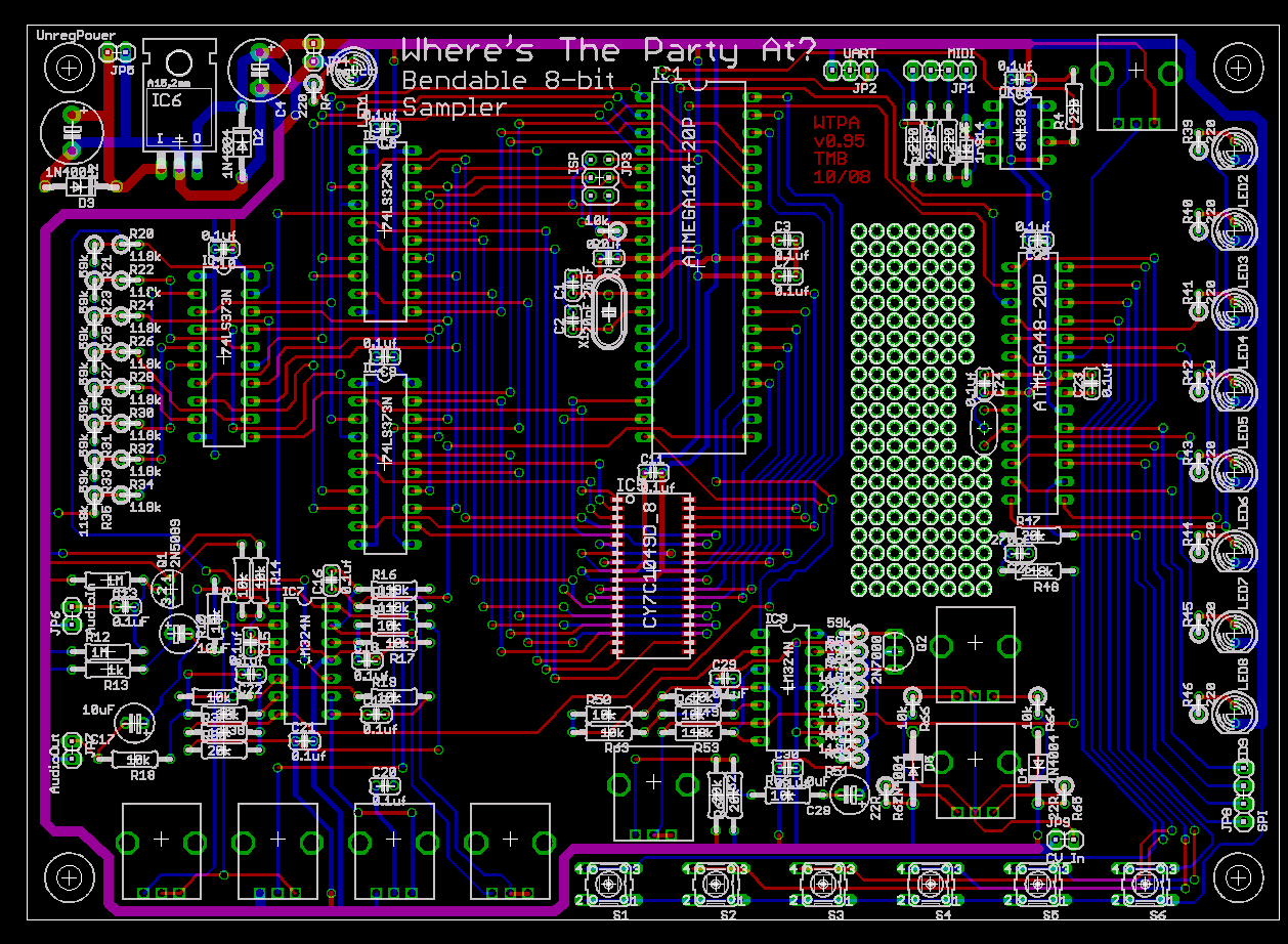
So I got the test PCBs Monday, bare as the day they were born. The last couple days I’ve been going through all the circuits and checking the hardware for problems, bugs, things to optimize, and stuff that would otherwise be Bad To Deal With in a run of 200 units.
The good news: The third rev of boards does more or less all the stuff it is supposed to, and has most of the performance improvements I’d expected. However, nothing is perfect.

First, let me give you young nerds a piece of advice. Become rich. Then use your dough to buy prototype boards that have a soldermask. Good lord. You will save yourself hours in debugging stupid soldering problems, and gray hair in debugging other problems which you may at first erroneously attribute to solder bridges.
Bare PCBs do offer an advantage in that they’re easy to probe wherever you need to, and all that exposed tin makes it easy to solder fixes in, but in general they will make you crazy at least once with some weird connection that you didn’t mean to make. That was the first round of problems I had to solve.

With those out of the way came the first real, serious, problem: The VCO. The VCO got incorporated in the last board rev and I dutifully wanked on it a few times and then set it aside to deal with other problems. This in retrospect was quite stupid, because if I had paid more attention I could’ve saved myself a lot of time and a little false advertising.
It turns out that the VCO design I used (ripped wholesale, with a few changes, from Horowitz and Hill p. 240, who I’m pretty sure in turn ripped it wholesale-with-changes from the LM324 datasheet) is good in many regards. It is single supply and simple. It requires only opamps and a fairly generic transistor or FET. The problem came in trying to tune the monster over a wide range. Though the TLV2474 opamps I’m using are pretty good at RRIO, they aren’t perfect.
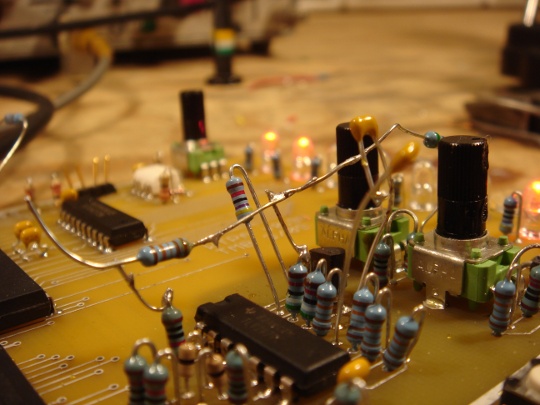
All the drama occurred when the CV was some small number of millivolts from the bottom rail. The ‘2474s don’t really want to drive that low, so I made the little Merce Cunningham looking mess of dancing resistors (pictured above) to help pull them there. Simple enough, but a little ugly.
Approaching REALLY closer to the rail (say within 10mV or less) the VCO stops responding in anything approaching a linear fashion and gets jittery and tends to drop out. Normally I wouldn’t care and would just bias the CVs above 10mV, but that ends up being a significant amount of tuning in the low-sample rate range. Which is silly. _NO_ op amp is that good, really, and no good design should try and expect one to be assuming it isn’t colliding particles or something.
With a marathon all-nighter / all-dayer the best performance I could get from the VCO was a not-so-great 2kHz to 16kHz, a tuning range of 8-to-1. This sucks. In retrospect the humble relaxation oscillator of the first WTPA did something like 60-to-1.

I fiddled around trying to get another VCO design breadboarded for a little while, but all the good ones I know use an OTA. I’ve seen some designs with analog switches and of course plenty with specialized VCO ICs, but I had three op amp sections and a dream. The final decision was to drop the VCO, return to the traditional relaxation oscillator, and reduce the opamp from a quad to a dual. Even Saving You Money(tm) in the process.

For those of you crying “Noooo! How will I make it talk to my Modular?” first let me say — samplers usually don’t talk to modular synthesizers, you’re spoilt. Second, let me say, because I love you, and because that’s a weird and cool idea, I’ve worked out a way to make the sampler’s oscillator clock sync up to audio inputs — so you’re losing a VCO, but you’re gaining a sync! This means that now you can synchronize your samples to your vocal line, synth line, guitar, or any signal in the audio frequency range.
This should work pretty reliably — I’ll know soon. I can no longer say “The only sampler with a VCO” but I think the new effect will probably be cooler anyway.

Everything else: I found a hardware bug in the in-circuit serial programming section related to changing around the data bus. I fixed with some pullup resistors. After that I made sure the switches and LEDs worked with the new bus structure. It’s technically still possible to PWM the LEDs and maybe I’ll do that sometime before release, but it’s low on the list. Next I quantified the bus-turnaround time related to the bus routing changes, and they’re almost invisible. It took some NOPs in the ISR, but I bet I can optimize those out later. I tested the MIDI output — so far WTPA has only received midi messages. But today it took charge, such as it can.
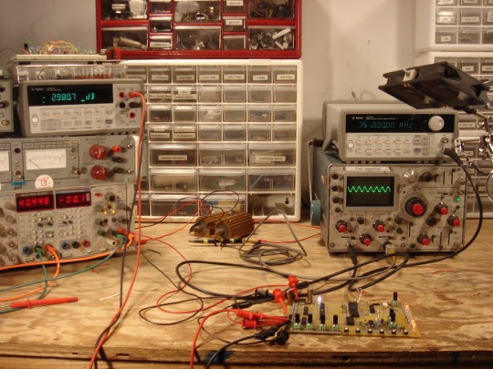
Finally, I took a look at the audio path. This was important and enlightening. Using a function generator and a fancypants benchtop meter set to take dB readings, I figured out the f3dB points for all the different audio paths through the system. They were pretty good — the first reading showed the audio range of the sampler’s pass-through and DAC paths to be about 14Hz-356kHz (pictured above). Not bad!
Still, as a rule of thumb (also ganked from H&H) I try and position f3dB points 10 times greater or less than the frequency of interest to avoid phase shifts in the audio range. You know what they say about phase shifts, right? “They make for weak ass west coast bass, not that Miami shit.” That’s what I heard them say.
Anyway, I got the range for those paths to be more like 2.8Hz to 370kHz with a few changes. In the overdub path I managed to actually DC couple some of the connections which means that there should be no loss in that path relative to the rest of the sampler.
Giving it the listen test, it sounds Really Good. I’m happy with the audio quality. It’s nice and quiet where it should be, with good frequency response, leaving it free to Expose Da Crust in all the important parts.

Finally, there was one more valid thing I found. In an effort to keep impedances (and costs) low I settled on two values of potentiometer for the final thing — a 500k audio taper for the input and output amp gain controls and 1k linear pots for everything else. In all the audio controls on the board, the 1k pots have a resistor from the wiper to ground to approximate a logarithmic curve (and make your life silky smooth). This means that the total resistance in some places in circuit ends up being pretty darn low. Although this does keep noise pickup low and the top f3dB point high, it also ends up working out the driving opamps something fierce. My hot rail-to-rail output doesn’t swing nearly as rail-to-rail as it used to. This of course means less usable bits in our sample. I can fix this a little by chaning the tapering resistors on the pots, but the right thing to do would be to bump the pots up to 10k and scale their related circuits. Easy enough, if I didn’t have a boatload of pots on the way from China already. The ENOB isn’t terrible, but it could be a little better. Hey, what’s a design if there isn’t room for revision?

Lastly, before I leave the soapbox, I’d like to take this opportunity to show this off as yet another example of an old TMB truism: Analog Be Harder Than Digital. Not better, but harder, and perhaps by association more noble and romantic.
While I was frantically breadboarding crappy VCOs, I came across this app note in which that continuous font of inspiration, Jim Williams, designs like 10 analog circuits which are complicated enough that they make my head spin even after reading his explanations, and he figures them out for shits in his garage or something, while on vacation. There’s a badass VCO in there which tests my understanding, and whose makeup is also (or consequently?) not quite right for WTPA.

Oh, and it also made me always remember to refer to VCOs as “Voltage to Frequency Converters” again. Saying VCO makes you sound like Jean-Michel Jarre; saying VFC makes you sound like a curmudgeon with a white beard and a bunch of Teflon caps and bandgaps. Who would you rather be?

Hello, big bag of Chinese boards? Perhaps you would like to come over?

Xoxoxo, TMB

Rev 0.95 Gerbers Up, New Design Decisions

Wednesday, October 8th, 2008

Yo! A lot has happened since the last time I posted here. For one I’ve organized this site more logically, with the most recent *ish at the top. But the most important thing is this:

I’m done with the new WTPA boards! Done, at least with the schematics and layouts. I’m currently printing up (another) prototype run of bare PCBs to work out any (who’s placing bets?) hardware bugs before I make the *BIG ORDER*. There’s a lot to say about the new designs, but, like the Roc Boys: Speech: First Of All I’d Like To Thank My Connects–

After Bent in the spring, four brave souls bought beta versions of WTPAs and –Lordy– all four really built them! Their contributions and comments on the process were invaluable to this latest version. MAKE Magazine and its denizens have hooked me up with a lot over the last year and most recently the opportunity to talk about WTPA at American Maker at the Museum of Science and Industry here in Chicago. That in turn led to some writeups on Create Digital Music and Hackaday and the resulting diarrhea-esque inbox explosion did a lot towards cattle-prodding me into getting this project rolling along better. It also felt really good. So, big propers to all of them, and all y’all who wrote to me with suggestions, requests, and kind words. Special thanks to Richard How for sending me a properly compressed version of the demo video that I listed below.

Now, sincere acts of ass-licking aside, let’s talk electronics:

Those of you who are dorks can probably tell that there are some differences between the latest boards and the first run. In that poetic way that HTML lets us do so well, here is a Canonical List of changes and features:

  • The RAM chip is now surface mount. This was a hard call b/c so many kit builders are put off by SMT, but 4 out of 4 beta testers (and 1 out of 1 Todd Baileys) wished they had more recording time, and the old memory chip was the biggest SRAM I could find in through-hole. So there’s now 512k of RAM as opposed to 32k — 16x as long sampling time. I promise that with a little practice and anything but the crappiest iron you can solder it.
  • The latches are parallel rather than serial latches. This means that there are fewer clock signals buzzing around the board, and the data rates are generally higher.
  • Support for the onboard PWM-based synth was dropped. It was pretty lame, and besides, this is a sampler.
  • There’s another op amp. This helps some (hopefully) cool stuff happen:
    • There’s way better separation between the quiet analog sections, the noisy analog sections, and the REALLY noisy digital sections. An 8-bit sampler is supposed to be crusty, but there were some really annoying whines that were a function of crap getting into the high impedance amplifiers.
    • Better pre-amp design.
    • The sample-rate clock is now a VCO. Originally I did this so that I could route a quiet control voltage to the frequency control pot instead of a noisy audio frequency square wave, but I figured while I was at it I could include a CV input, too.
    • The gain mismatch between sampling and overdubbing should be fixed.
    • There’s an exciting new error source to tweak: CLOCK JITTER! In the spirit of exploring cool sounding sampling “flaws” (like low bit-depth, aliasing, low sample rate, etc) I included a circuit that lets the user optionally add an adjustable amount of jitter to the clock. We’ll see how that sounds, but I’m excited.
  • I decided to add a SECOND microcontroller (and lose a latch). This guy mostly handles the switches and LEDs, and generates a PSRB as a noise source for the jitter generator. This is a little bit of a splurge, but it frees up pins (and some cycles) on the main MCU for cooler things (like parallel interfaces and more RAM lines) and allows us to PWM the LEDs, which just looks cool. It also allows us a deicated SPI interface which we could conceivably interface to permanent memory, like an SD Card. That’s pretty low on the priority list for me, but it’d be a really cool feature to add later.
  • Another practical upshot of this is more switches in user interface. The menu system on the old one was a little byzantine to some people (and sometimes me).
  • MIDI is fully implemented. MAN, this was a huge improvement! I use my beta version with an MPK49 all the time and it’s SOOOO much better than fiddling with little knobs and tact switches. It’s a priority of mine to make sure this works with Ableton Live before I release the final revision.
  • Probably some other stuff I’ve forgotten.

As well as another heartrendingly beautiful, autumn-sunset-like list of FAQs, gathered from emails and the like:

  • When can I buy one?
    • Soon. Soon? Before the holidays, I think. Is that soon?
  • Why so long?
    • I’ve got an OS to re-write, and testing to do as well as a lot of logistical stuff like hounding Chinese factories to send me parts, which is about as much fun as mowing the lawn. Or HTML.
  • How much will they cost?
    • I’d rather not say on the site, mostly because I’m honestly not sure. There are still enough pending weird money chats with distributors and stuff that I can potentially put my foot in my mouth pretty seriously.
  • Where’s the source, you dingus? You said this was open source!
    • Yeah, yeah. It is. Sorry. But while I’m still tweaking everything it’s a pain in the ass to maintain a public version. The PCB isn’t final yet, the code has potential bugs and unimplemented, un-optimized stuff, and I’d rather spend my time knocking out features and fixes than answering email. This is a little selfish, perhaps, but rest assured that once I release the real thing you will likely have more gibberingly verbose C code and notes than you care to read. I promise :-)
  • How’d you learn this stuff?
    • A lot of twiddling with a scope. Read this, get an oscilloscope and a breadboard, pick an anlog project that you love, do it, then learn how assembly code works, do a project with it, and finally make friends with GCC. It really, really helps to love what you’re doing. I think about electronics when I’m on dates and stuff (although I didn’t always. Give it time. And don’t blame me for the obvious wet blanket this will toss on your pimp game).
  • Are you completely and utterly on the jock of Jim Williams?
    • As a matter of fact, I am :) I have a lot of other personal mentors to whom I owe volumes and who I won’t embarrass by mentioning on this site, like this guy who taught me pretty much everything I know about C programming.
  • Do you Twitter?
    • Embarrssingly, yes.