God, it’s been so long I hardly know what to say. But I believe the big banner above says the most important thing :-)
It is with excitement and not a little trepidation that I am announcing WTPA’s booting out of workbench land and into the hard, cold world.
That’s right: The wait is almost over — the real deal kits WILL BE out for the Bent Festival in New York this April! Not my usual, waffly “soon”. But on a real, fixed, finite date!
That’s exactly one year since the proto came out, and would be embarrassingly slow if the latest WTPA wasn’t head and shoulders better than its forefather. But. Lest you think I’ve been idle, know that since my last post I have done several things:
- I have become a business. Not a sissy nonprofit either.
- I have used my extensive pull in the “business” world to do some international commerce, and have a boat full of components on the way from Taiwan.
- I’ve set up (and am continuing to set up) an “E-commerce solution”. Although I like these about as well as I like “blogs” and “hipster runoff” they are all totally unavoidable in 2009.
- I’ve revised the dickens out of the boards.
- And all of this is to sell you kits!
The first run of kits will number 0-199. This figure made the most sense considering all the number crunching I did, at least for now. The retail price will be announced on or around the release date, but for the curious it will be nestled snugly somewhere between Mssrs Grant and Benjamin.
There may, at some point, be another distributor besides Narrat1ve for this kit, but they will not likely be onboard by the release date. The kit will come BYO-enclosure, although I will probably sell some parts on the site to make it easier for those of you who want a little of the guesswork taken out. The website will (has to, basically) get beautified to accomodate info for the people building the kit, and not so much my gibbering. Finally, on (or right around) the release date, you’ll be able to get ahold of the source, schematics, instructional videos, manual, and theory of operation docs all from right here.
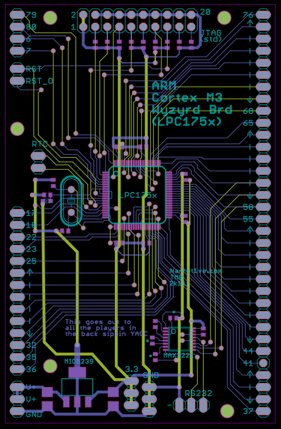
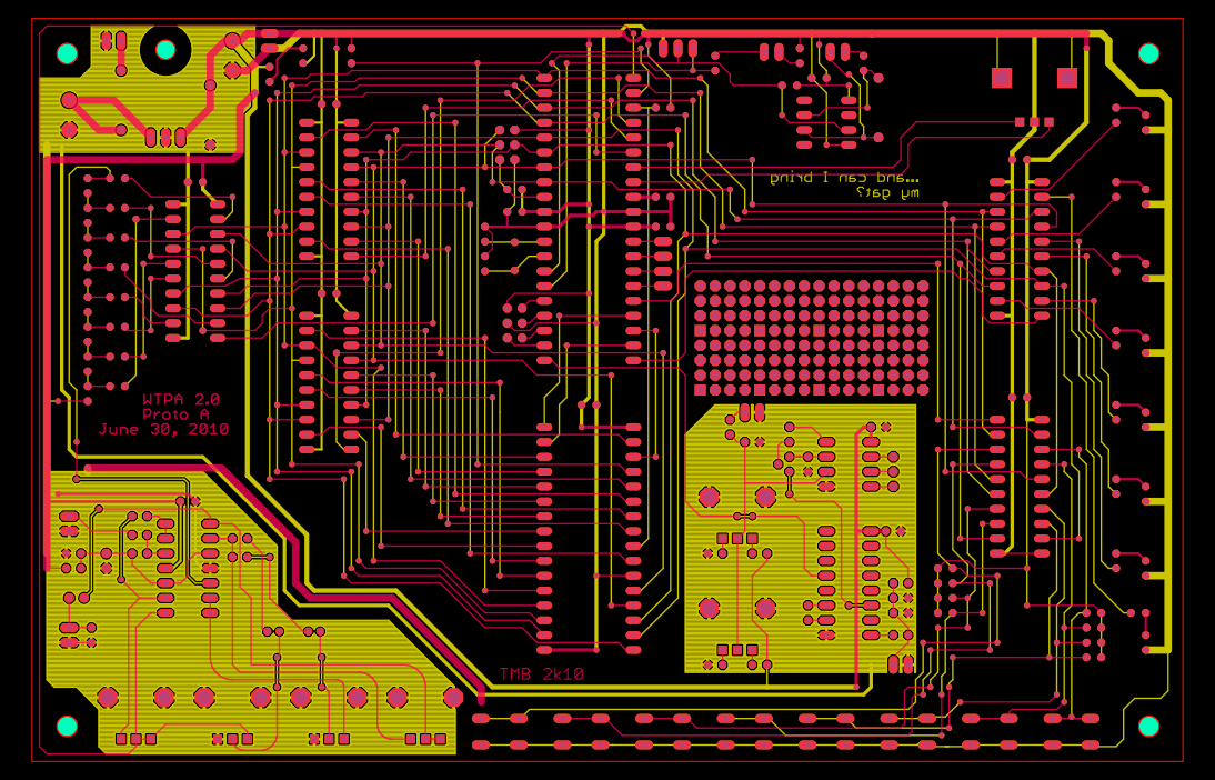
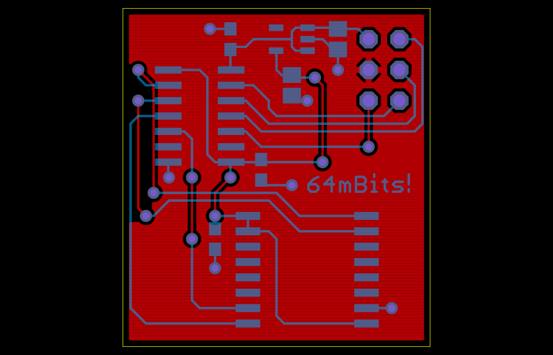
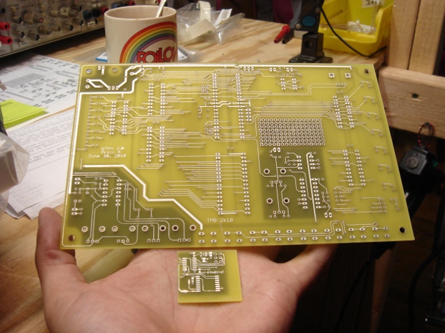
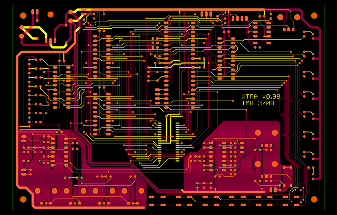
The hot mess you see above is the test pressing of the final WTPA boards (it’s a picture of the gerber files, complements of GEDA’s Gerbv, which (sadly) unlike most of GEDA, totally rules). The real thing gets here Monday for requisite twiddling.
This is the third and last (hopefully) major hardware revision WTPA will go through. The second WTPA totally slayed the first in audio quality, latency, functionality and pretty much everything else. This last rev cleans up the rough spots that were still left on the second rev, and adds a sprinkle of small new features.
Mostly, however, it is the physically smallest and most simplified of the WTPAs to come out yet and is geared to make the kit easier to build and cheaper to sell. There is very little fat left on this design in my opinion.
Technically, WTPA has returned to single-MCU design. Shortly after I made the two-MCU rev I learned about a device called an I/O expander, which is cheaper, simpler, and more robust than a goofy UART link with a second MCU. Shortly after beginning to do battle with the I/O expander I did some much needed forehead-smacking and figured out how to rearrange the databus and replace the whole nasty expander / MCU / mess / with another parallel latch. Which of course was the Right Answer. Pie-simple, cheap, effective.
This WTPA also has its two analog subsystems (the input/output amps and the VCO / CV section) isolated with separate ground planes and ground returns to the main regulator. The last WTPA was not noisy, but I expect this one to be even better. The goofy emitter follower in the front end has been removed. This should result in better audio response, more headroom, and fewer parts.
The jitter generator has been moved into the realm of software. This does a lot for us. Most importantly, it makes the jitter work right (and sound cooler). It also introduces less HF noise onto the board, and further reduces the parts count. Finally it allows the jitter to be controlled by MIDI! This is obviously good for playability reasons, but it’s “orthoganally good” as well because the jitter clock was the only effect left exclusively in the analog domain. Other than the gains, everything on WTPA is now controllable from both the knobs and switches AND the MIDI in.
Finally, all this hardware juggling allowed me to free up a few extra pins which I assigned to a spare UART / SPI module. I have no immediate plans to expand WTPA, but if I ever did, this would be a great way to do it (say, to talk to other instruments or to add an SD card interface or the like).
This all means that the hardware is basically done changing. It also means I’m getting down to the wire on software business, too. WTPA will not go gently into the aforementioned good night — expect to see LOTS of updates here for the next month while I pull all-nighters getting this monster ready for her catwalk. There will be some ugly fixes, a huge rush of features, sample banks, scope traces, the whole nine. Exciting stuff!
And hey, thanks so much for sticking around this long. Xoxoxo.