Boom! Current sinks all the way:
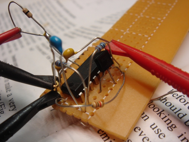
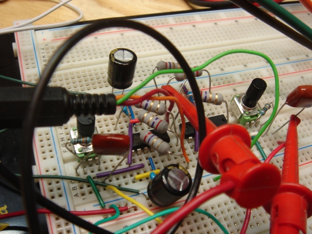
Because I am late to a BBQ I will not bother here to kick on the corporate dog and grumble about how not a single Rat Shack in downtown Brooklyn sells solderless breadboards. I will however sing the praises of H&H (buy that book. I’m not kidding) and the value of the current sink in the previously discussed VCO clock circuit. I soldered this mess up on some perfboard and in short order had a VCO that happily went from DC to >> 1MHz! The linearity is TERRIBLE, but it proves that the range is there. I’m pretty sure I can fix it adequately for my needs with just fiddling with the passive components in this circuit. Hopefully. Here’s the schematic, captured in time honored analog fashion:
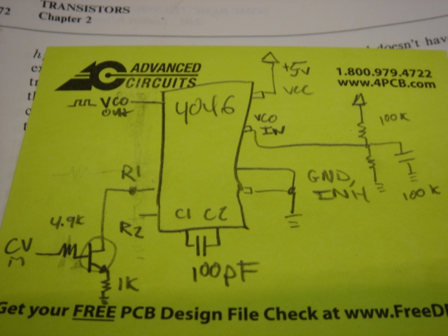
Those component values are way stupid, but I think this is the topology. I may yet get away without the op-amp. Live and learn. And happy BBQing.
xo
TMB
323 | posted at June 12th, 2010 in Uncategorized | Tags: Analog, Books I Like, PLLs, VCOs / VFCs, WTPA, WTPA v2.0
So once again somebody on the forum came through and found this guy’s page about designing a switched capacitor filter, where he talks about using a CURRENT SOURCE (sink, actually) instead of a resistor on one of the 4046’s frequency setting pins. This was a real forehead smacker. Thanks Kyle (erschlagener) for the heads up, and thanks to Tim for putting that out there in the first place!
Requisite googling found an EDN note about this, too:
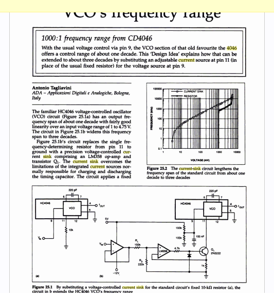
Which claims a 1000:1 frequency range out of the 4046’s VCO!
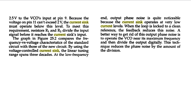
It also confirms what I’d found on the breadboard before, namely that the 4046’s frequency output is not particularly linear outside of about 1v-4.75v, and that inside there you can expect to get about a decade of range. So I felt less dumb.
This note also has the bright idea of putting the sink in the feedback loop of an opamp, which almost certainly helps linearize the sink’s behavior at low voltages by getting rid of base current related weirdness.
Enter a quick trip to findchips for some pricing data. Turns out that the 4046 and a transistor are certainly cheaper than the LM331, although they take up more real estate. Even throwing in an cheap LM358 still costs less than the LM331, although the savings start to get less significant. Now, if there was some good use for that second op-amp in a ‘358, that’d be something…
This recalls some quote I heard and want to attribute to Jim Williams, though I can’t recall exactly where it’s from, about how in modern circuits like 80% of the thing is digital and takes 20% of the time to design, whereas the 20% that’s analog takes the 80%. Sometimes it does seem true, although it might just be (for me anyway) that the analog parts are a lot of fun :-)
Back to the breadboard!
xo
TMB
286 | posted at June 9th, 2010 in Uncategorized | Tags: Analog, Analog Be Harder Than Digital, App Notes, PLLs, VCOs / VFCs, WTPA, WTPA v2.0
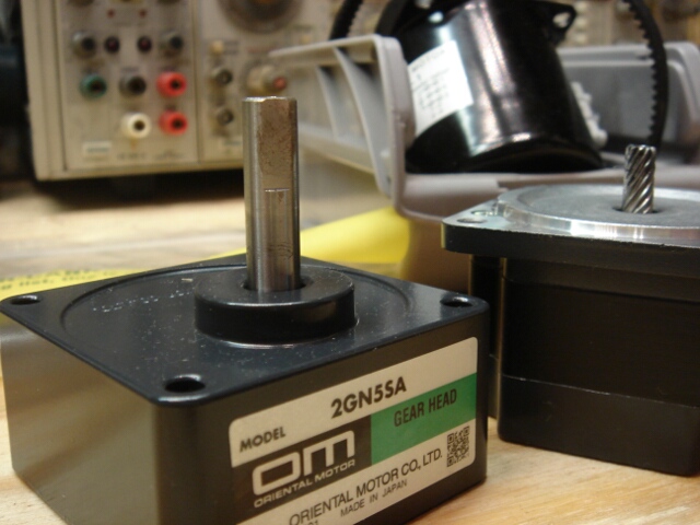
So, because it isn’t actually in a show yet I can’t talk about what this new dancing stand is for, but it may or may not be capable of beating up Robocop. Suffice it to say, the old gearmotor has been removed from this stand and replaced with a two-pound tank which comes as a separate synchronous motor and gearhead.
This also continues the fascinating if slightly worriesome Spring 2010 trend of my clients viewing me as a one stop for assembly language and abrasives, but things are slow so I’ll take it.
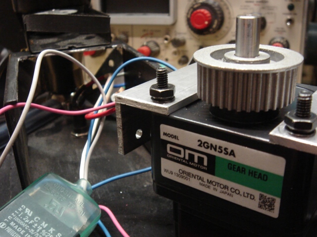
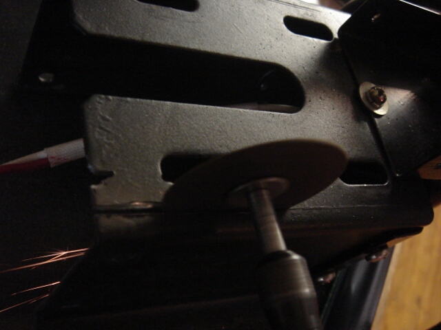
The new gearmotor was similar in size to the old one, but not so similar that it didn’t mean cutting out a big piece of the steel doghouse, making some aluminum mounts to hold the motor, drilling out the timing pulleys to fit the new motor shaft, and putting a detent in said shaft to seat the set screw. I also got my first set of metric taps, so that I could use M4 screws in this guy and the hardware I put in would match the hardware from the factory. This, O art world, is the attention to detail you get when you hire C Programmers to get their thread-cutting on.
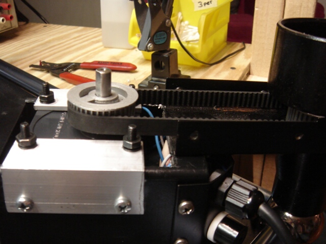
Here she is all buttoned up.
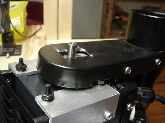
Though I have a sneaking feeling Cory doesn’t really care about what the bottom of these things look like, I kinda do. Plus I figure the dust cover, you know, keeps dust out. Plus I had just gotten these really cool carbide burs and I was excited about cutting more holes in stuff.
Perhaps one day, one of these things will have a stepper motor or optical encoder or SOMETHING with silicon in it and everything will come full circle.
267 | posted at June 7th, 2010 in Uncategorized | Tags: Art Shiz, Contract Work, Cory Arcangel, Hardware, McMaster, Tap Magic
So a few weeks ago I met up with my old buddies Limor and Phil at Adafruit Industries and was griping about work being slow, and they were like, design us a kit.
So I did. They wanted a headphone amp which, in their words, “didn’t suck”.
This was really exciting to me! I do a lot of contract work, but I almost NEVER get to do something that’s exclusively analog! Granted, an HPA is not exactly pushing the boundaries of silicon magic in 2010, but I’ll take what I can get. It was a blast. I got to figure out phase margins and characterize ringing and overshoot and make a cable mess (and then worry about the capacitance of it) and just generally get my party on. Plus it was a chance to flex skills in an arena that is full of a lot of crappy designs.
And though the thing is GPL’d,, they did ask me not to go into specifics here or post any schematics or juicy bits UNTIL they have the product out, so until that happens I’m afraid I can’t go into a lot more detail.
Can’t wait to see them lay it out.
Thanks guys!
ALSO — I’d be remiss in not mentioning my friend Shea who had a lot of great advice on this circuit and who has generally forgotten more about audio electronics than I’ll ever know. He re-did the Trident A Range board at Soma Electronic Music Studios when I was back in embedded diapers and let me help re-cap some modules and generally be a solder monkey. I got paid $10 an hour for that and those were still some of the most exciting electronics dollars I ever made.
221 | posted at June 5th, 2010 in Uncategorized | Tags: Adafruit, Analog, Chicago Represent, Contract Work, Device Characterization, Hardware, Kits
First beta WTPA 2 release date got announced on the Narrat1ve Forum today. I promise to have pictures of a more-or-less-working printed circuit board HERE by July 1st. I’ve already got a rep at Future who I think can save me some dough in parts sourcing, which is good, and I’ve got initial hardware specs (RAM, rotary encoders, new MCU etc) done. The board is starting to come together too. Once all that happens the firmware will start to get changed and I’ll make sure the pretty case fits and looks nice.
278 | posted at May 31st, 2010 in Uncategorized | Tags: Design Goals, Device Characterization, Hardware, Kits, Parts Sourcing, WTPA, WTPA v2.0